Interference-compensated sensor

a sensor and compensation technology, applied in the field of interference compensation sensors, can solve the problem that the signal existent at the amplifier output will normally not be a true zero signal anymor

Active Publication Date: 2011-12-01
MECHALESS SYST
View PDF4 Cites 6 Cited by
  • Summary
  • Abstract
  • Description
  • Claims
  • Application Information

AI Technical Summary

Benefits of technology

[0026]In the most simple embodiment, each of the first and second subtractors can be formed as a connecting node of the outputs of the measurement and reference branches of the r

Problems solved by technology

However, the signal existent at the amplifier outp

Method used


Image

  • Interference-compensated sensor
  • Interference-compensated sensor
  • Interference-compensated sensor

Examples


Embodiment Construction

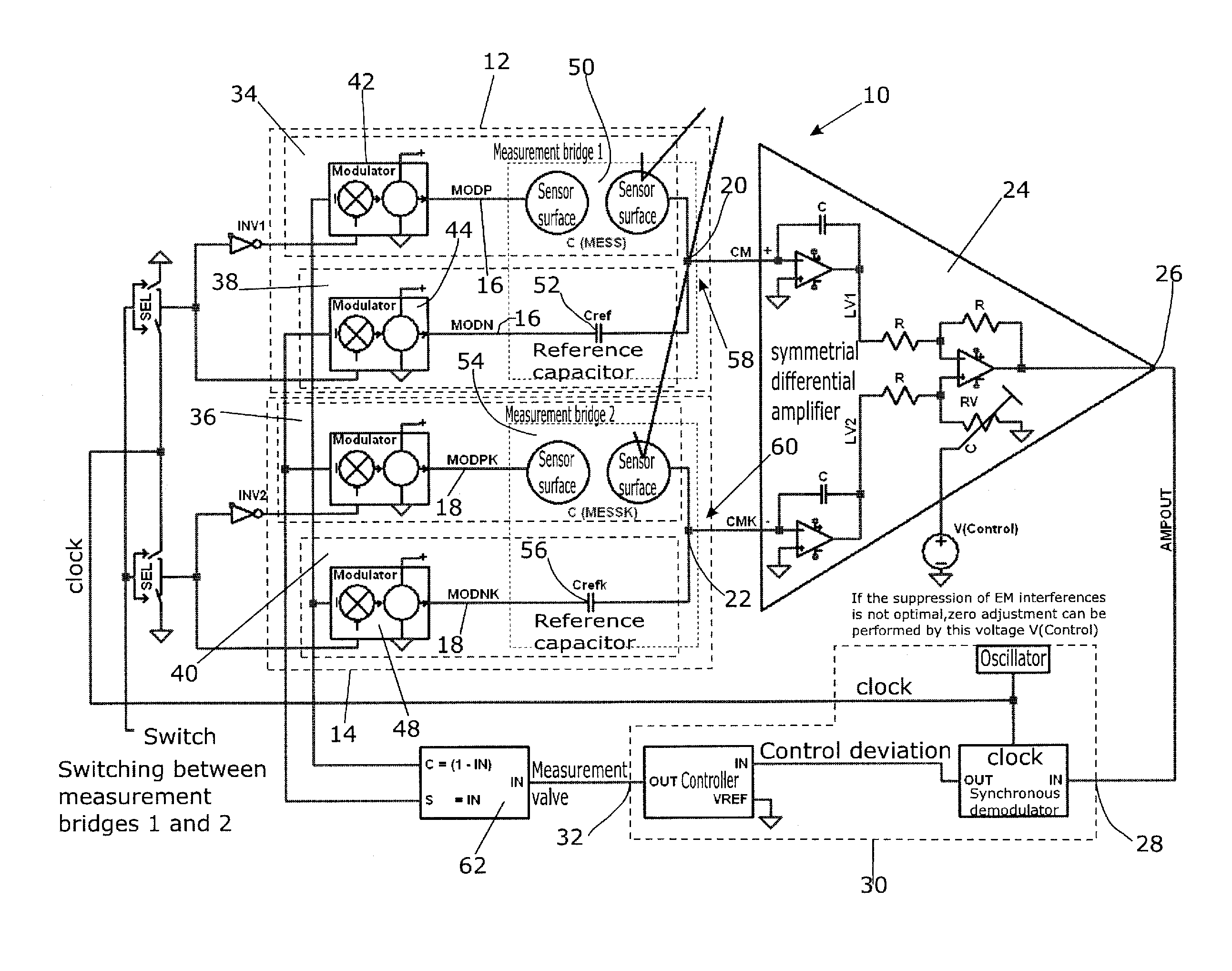
[0051]The block diagram shown in FIG. 8 represents the layout of the sensor for measurement of electric parameters in a random linear RLC network. What is measured are the changes of the parameters of RLC network elements 50,54 in comparison with the reference RLC network 52,56.

[0052]Now as before, a good EMW demands that the disturbing incident radiation enters the two sensor networks of the sensor (measuring) bridges 12 and 14 to the same extent (symmetrically).

[0053]The control of the two measurement bridges 12 and 14 can be performed simultaneously or sequentially in time. FIG. 8 illustrates the case for simultaneous measurement. In this case, the clock signals of all four modulators are active during measurement. In the general case, when the RLC parameters of the two sensor networks do not fully coincide in their branches 34,38 and 36,40, respectively, a cancellation of the useful signal to zero will occur only at the node AMPOUT 26 and indeed not at the summation points CM 20...


PUM


Abstract

The interference-compensated sensor (10) for detecting an object located in a detection area in a contactless manner, particularly a rain sensor, is provided with a first and a second measuring channel (12,14) each having a control device and an output (20,22), wherein both measuring channels (12,14) are substantially identical. The sensor (10) further comprises a main subtractor (24) having an output (26) for outputting the difference of the signals at the outputs (20,22) of the measuring channels (12,14). The sensor (10) is provided with a controller unit (30) having an input that is connected to the output (26) of the main subtractor (24) and with an output for outputting a controller signal, by means of which the two measuring channels (12,14) can be controlled in such a way that the signal at the output (26) of the main subtractor (24) can be controlled to zero. By means of the magnitude of the signal at the output of the controller, it can be determined if an object is located in the detection area.

Description

SUBJECT MATTER OF THE INVENTION[0001]The invention relates to an interference-compensated sensor for contactless detection of an object located in a detection area, said object being e.g. a raindrop impinging particularly onto a windshield. Thus, the invention particularly relates to an interference-compensated rain sensor.BACKGROUND OF THE INVENTION[0002]Sensors which generate their (actual) output signal within the framework of a compensation method in a control process, are widely known.[0003]For instance, EP-B 0 706 648 describes a method which is also known under the name “Halios” and can be applied to optical, capacitive and inductive sensor systems.Halios Realization with RC Low-Pass Filters[0004]The mode of operation of a capacitive sensor based of these measurement methods is schematically illustrated in FIG. 1. At the nodes MODP and MODN, two push-pull signals which can be modulated in their amplitude, are fed into a measurement bridge consisting of two low-pass filters. T...

Claims


Application Information

Patent Timeline
IPC IPC(8): G06F19/00G16Z99/00
CPCB60S1/0825G05B11/011G06F17/40G06F19/00G01R17/06G16Z99/00B60S1/08
Inventor MELCHER, ROLFMUSCH, ERHARDSCHWENINGER, ERHARDZAWACKI, ROBERTO
Owner MECHALESS SYST
Why Eureka
Try Eureka