Ignition apparatus of plasma jet ignition plug

a technology of ignition plug and ignition apparatus, which is applied in the direction of ignition control, other installations, machines/engines, etc., can solve the problems of high igniting limit fuel efficiency, and achieve the effect of preventing electric nois

Inactive Publication Date: 2011-12-08
NGK SPARK PLUG CO LTD
View PDF17 Cites 14 Cited by
  • Summary
  • Abstract
  • Description
  • Claims
  • Application Information

AI Technical Summary

Benefits of technology

[0035]According to an ignition apparatus of a plasma jet ignition plug of the present invention, at the ignition of a plasma jet ignition plug, a current of sufficient size for forming plasma flows at a spark discharge gap and also occurrence of electric noise is prevented.
[0036]As described above, the present invention has been concisely described. Also, by carefully reading the following described preferred embodiments in reference to the annexed drawings, the details of the invention will be further elucidated.

Problems solved by technology

In recent years, a plasma jet ignition plug in which the expansion of combustion is speedy and which can be surely fired for lean mix gas having high igniting limit fuel efficiency has been used as an ignition plug since a high output and low fuel efficiency of an internal combustion engine are required.

Method used


Image

  • Ignition apparatus of plasma jet ignition plug
  • Ignition apparatus of plasma jet ignition plug
  • Ignition apparatus of plasma jet ignition plug

Examples


Embodiment Construction

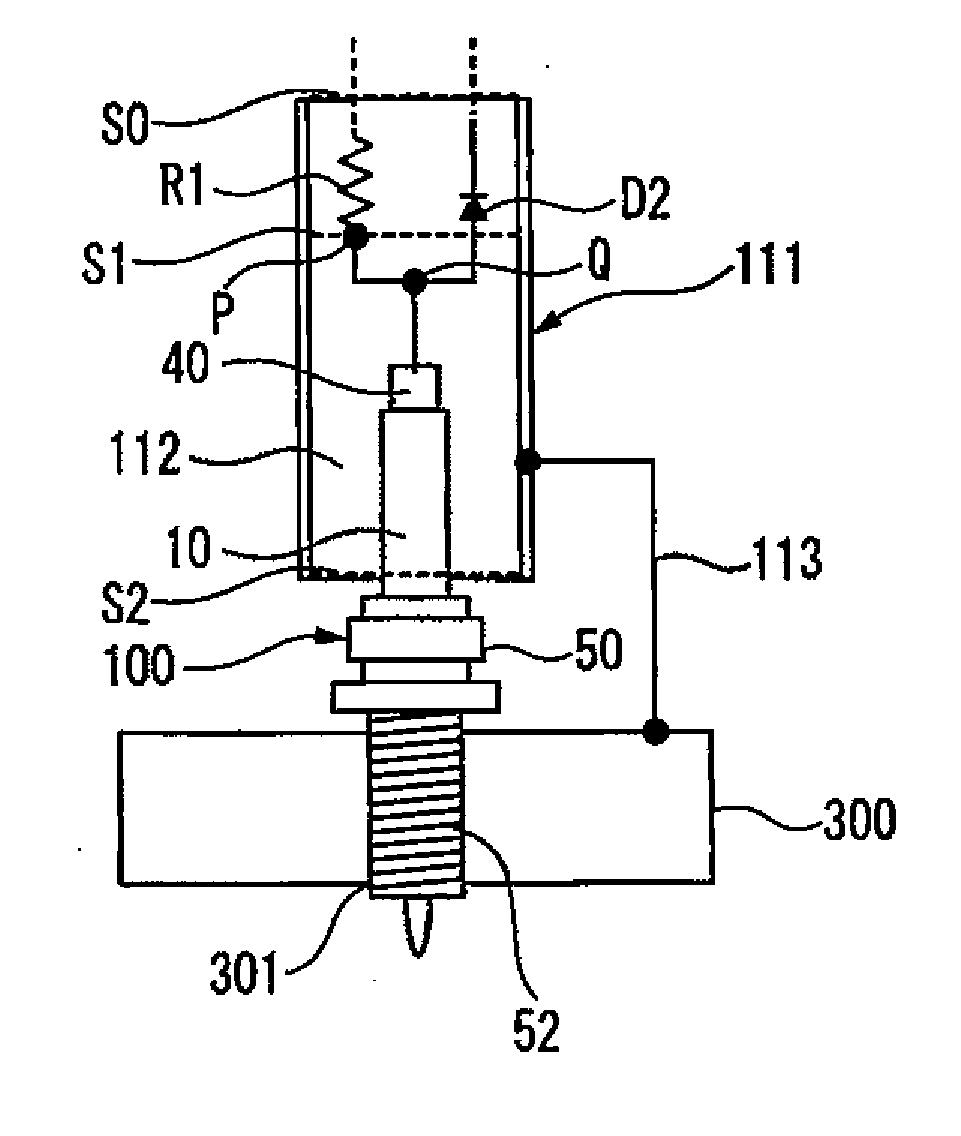
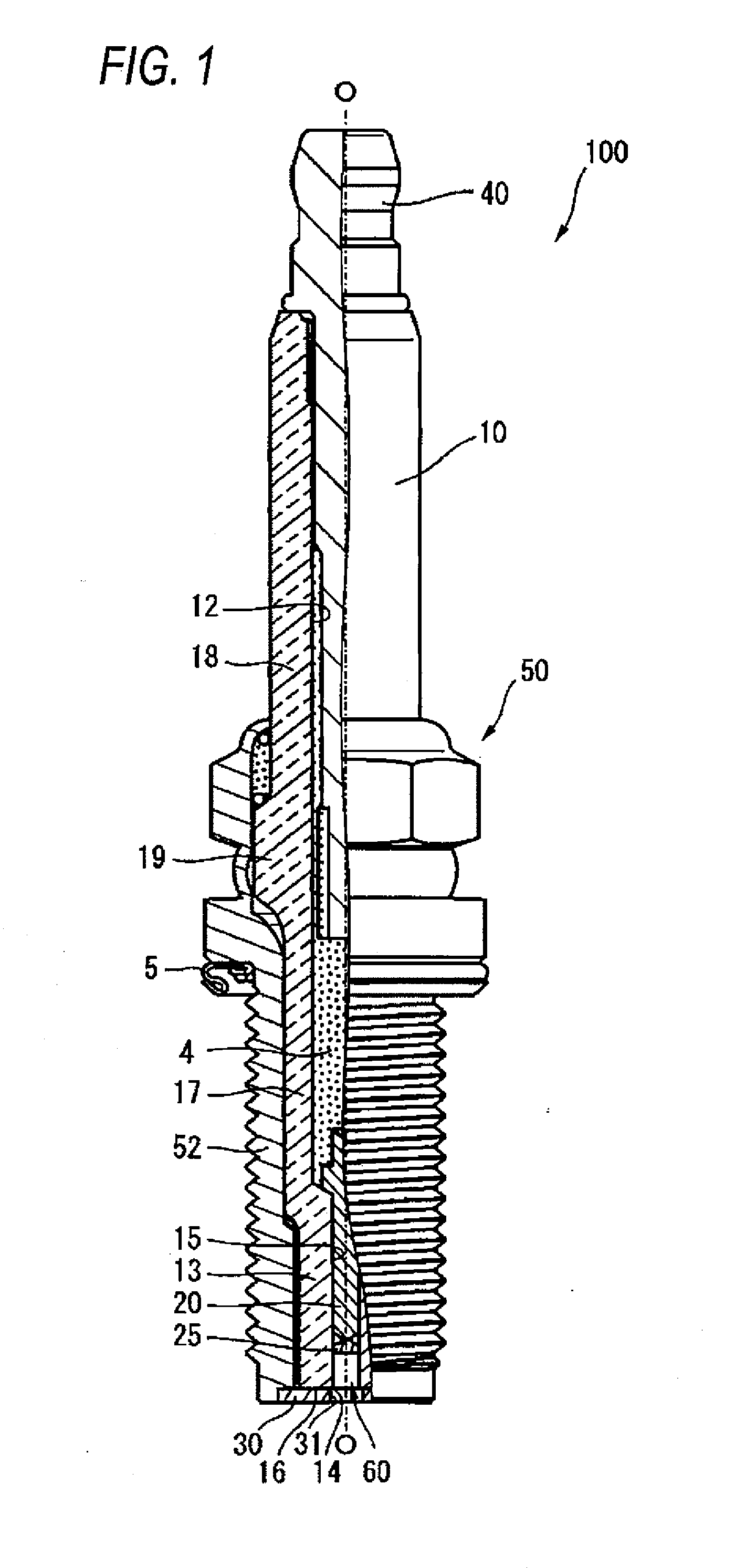
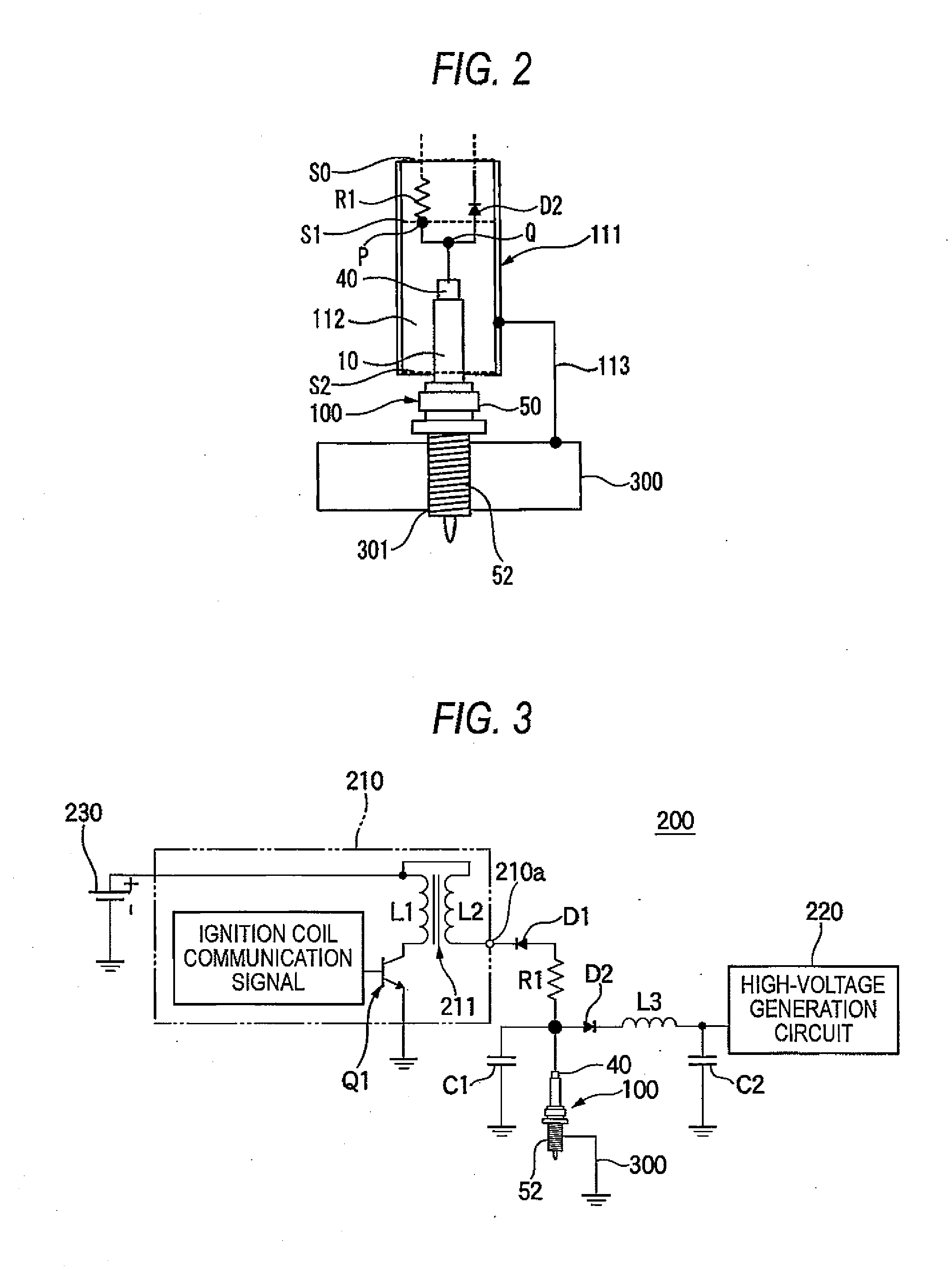
[0041]Hereinafter, one embodiment of an ignition apparatus for a plasma jet ignition plug according to the present invention will be described with reference to drawings. First, a plasma jet ignition plug 100 will be described. A basic structure of a plasma jet ignition plug 100 usable in an ignition apparatus 200 of the present invention is shown in FIG. 1. In FIG. 1 an axis direction O of the plasma jet ignition plug 100 is defined as an upward / downward direction in the figure, the lower side is described as a frond end side of the plasma jet ignition plug 100, and the upper side is described as a back end side.

[0042]The plasma jet ignition plug 100 shown in FIG. 1 is formed from an insulating member obtained by sintering alumina using a well known method, and has an insulator 10 of cylindrical shape formed with a shaft hole 12 extending in an axis direction O. The insulator 10 has a center body part 19, which has a biggest outer diameter and is centered in the axis direction O. A...


PUM


Abstract

A current of sufficient size to form plasma at ignition of a plasma jet ignition plug flows to a spark discharge gap while suppressing noise occurrence.
There is provided an ignition apparatus of a plasma jet ignition plug, which includes a resistor R1, with one end connected to a diode D1 disposed between the plasma jet ignition plug 100 and a high-voltage generation circuit 210 and with the other end electrically connected to a center electrode 40 of the plasma jet ignition plug 100, and a capacitor C1, with one end connected to the center electrode 40 of the plasma jet ignition plug 100 and with the other end grounded.

Description

TECHNICAL FIELD[0001]Apparatuses consistent with the present disclosure relates to an ignition apparatus of a plasma jet ignition plug for an internal combustion engine performing the ignition of mixed gas by forming plasma.BACKGROUND ART[0002]In the related art, a spark plug performing a firing of mixed gas by spark discharge (simply referred to as ‘discharge’) is used for an igniting plug of an engine, for example, an internal combustion engine of automobiles. In recent years, a plasma jet ignition plug in which the expansion of combustion is speedy and which can be surely fired for lean mix gas having high igniting limit fuel efficiency has been used as an ignition plug since a high output and low fuel efficiency of an internal combustion engine are required.[0003]In such a plasma jet ignition plug, a spark discharge gap between a center electrode and a ground electrode is formed when connected to an electric source. A plasma jet ignition plug surrounds a vicinity of this spark i...

Claims


Application Information

Patent Timeline
Patent Type & Authority Applications(United States)
IPC IPC(8): F02P3/06
CPCF02P9/007
Inventor NAKANO, DAISUKESATO, YOSHIKUNIKAMEDA, HIROYUKIYAMAMURA, NAOFUMIKASAHARA, DAISUKE
Owner NGK SPARK PLUG CO LTD
Why Eureka
Try Eureka