Metal tube with porous metal liner

a metal tube and liner technology, applied in the field of metal tubes, can solve the problems of insufficient use of conventional metal foams in many heat pipes, small capillary force, and inability to meet the demand of heat transport capability in the industry, and achieve the effect of better controlling the thickness of the porous liner

Inactive Publication Date: 2011-12-08
METAFOAM TECH INC
View PDF0 Cites 51 Cited by
  • Summary
  • Abstract
  • Description
  • Claims
  • Application Information

AI Technical Summary

Benefits of technology

[0013]It is also an object of the present invention to provide a metal tube with a wicking structure that is improved when compared with at least some of the prior art metal tubes with porous liners.
[0014]It is another object of the present invention to provide a method for making a metal tube lined with porous liner. It is a further object to better control the thickness of the porous liner for use a metal tube with porous liner during its manufacture.
[0025]It is preferred that the outer wall of the metal foam liner is thermo-conductively bonded to the inner wall of the metal tube via sintering. Sintering has the advantage of not having to introduce an additional material during the making of the metal tube with porous metal liner. In some cases, where the addition of a brazing agent is not an issue, the outer wall of the metal foam liner is thermo-conductively bonded to the inner wall of the metal tube via brazing.
[0029]It is preferred that, for certain applications, the metal liner is heterogeneous. A heterogeneous metal liner can be constituted of more than one type of metal foam, and / or more than one type of sintered powder liner. Heterogeneous liners are preferred when different properties of the metal liner are exploited at different spatial locations. In one embodiment, the metal foam liner is shorter than the metal tube, and a sintered powder liner is thermo-conductively bonded to at least a portion of the inner wall of the metal tube where the metal tube is not lined with the metal foam liner. As an example, in a heat pipe made form a metal tube having such a metal foam and being used to cool the CPU of a computer, one can use a heterogeneous liner to have increased heat transfer to the heat pipe in the area adjacent to the CPU, and decreased heat transfer from the heat pipe in the adiabatic section, so as to cool the CPU with greater efficiency. For example, the heat resistance of a metal tube with an homogeneous metal foam liner above the CPU at 35 W is about 0.5° C. / W (calculated using the temperature of CPU−Tjunction—and the temperature at the surface of the metal tube on the other side of the contact with the CPU−Tevaporator). A maximum heat load capacity of the metal tube with the homogeneous metal foam liner in the adiabatic and condenser sections is more than 35 W. By contrast, a metal tube with a homogeneous sintered powder liner has a heat resistance of about 0.3° C. / W above the CPU at 35 W and a maximum heat load capacity of no more than 35 W. As well, the sintered powder liner has a smaller wicking speed than the metal foam liner. Therefore, a heterogeneous liner wherein a sintered powder liner portion is located above the CPU and a metal foam liner portion is located in the adiabatic and condenser sections, would allow one to exploit the low heat resistance of the sintered powder liner above the CPU and the high wicking speed of the metal foam liner in the adiabatic and condenser sections, which would lead to a maximum heat load capacity relatively higher than a metallic tube with sintered powder lining alone.
[0034]It is preferred that the mandrel be longer than the metal tube, and the method further comprises adjusting the mandrel in the tube-liner assembly so as to have ends of the mandrel extending on each side of the tube-metal liner assembly, before applying the heating treatment. The mandrel provides uniform applying radial compression onto the inner wall of the tube-liner assembly. Previously, in prior art metal tubes with sintered powder liners, the mandrel was secured at one end only, and the other end would be free to move and would create zones where the thickness of the sintered powder liner was not uniform. A uniform distribution of the thickness of the metal foam liner is desired for achieving greater results.
[0052]The term ‘substantially equal’ refers to a dimension that is equal or slightly larger or smaller than the quantity it is compared to, to the extent that it does not lead to unwanted material alterations that are incompatible with the intended use.

Problems solved by technology

Even though sintered powder liners are widely used in heat pipes, they are becoming no longer able to meet industry demand in terms of heat transport capability.
Despite being interesting candidates for wicking structures, conventional metal foams have in some situations been found inadequate for use in many heat pipes.
Conventional metal foams have large pore sizes leading to a large capillary radius, which leads to a small capillary force.
As such, conventional metal foam generally cannot pump the working fluid fast enough for adequate heat pipe performance.
Furthermore, conventional metal foams tend to have a microstructure and a high porosity (typically above 90%) that makes bonding (both mechanical and thermally conductive bonding) between the metal foam and the inner wall of the metal tube difficult.
These conventional techniques do not enable one to effectively control the thickness of the wicking structure formed in between the mandrel and the metal tube.
Small displacements of the free end of the mandrel within the tube and small curves in the mandrel itself result in a wicking structure having a thickness that is not uniform.
This lack of uniformity, along with zones of the wicking structure being deformed from over-compression typically negatively affects wicking and heat transfer capacity performances.

Method used


Image

  • Metal tube with porous metal liner
  • Metal tube with porous metal liner
  • Metal tube with porous metal liner

Examples


first embodiment

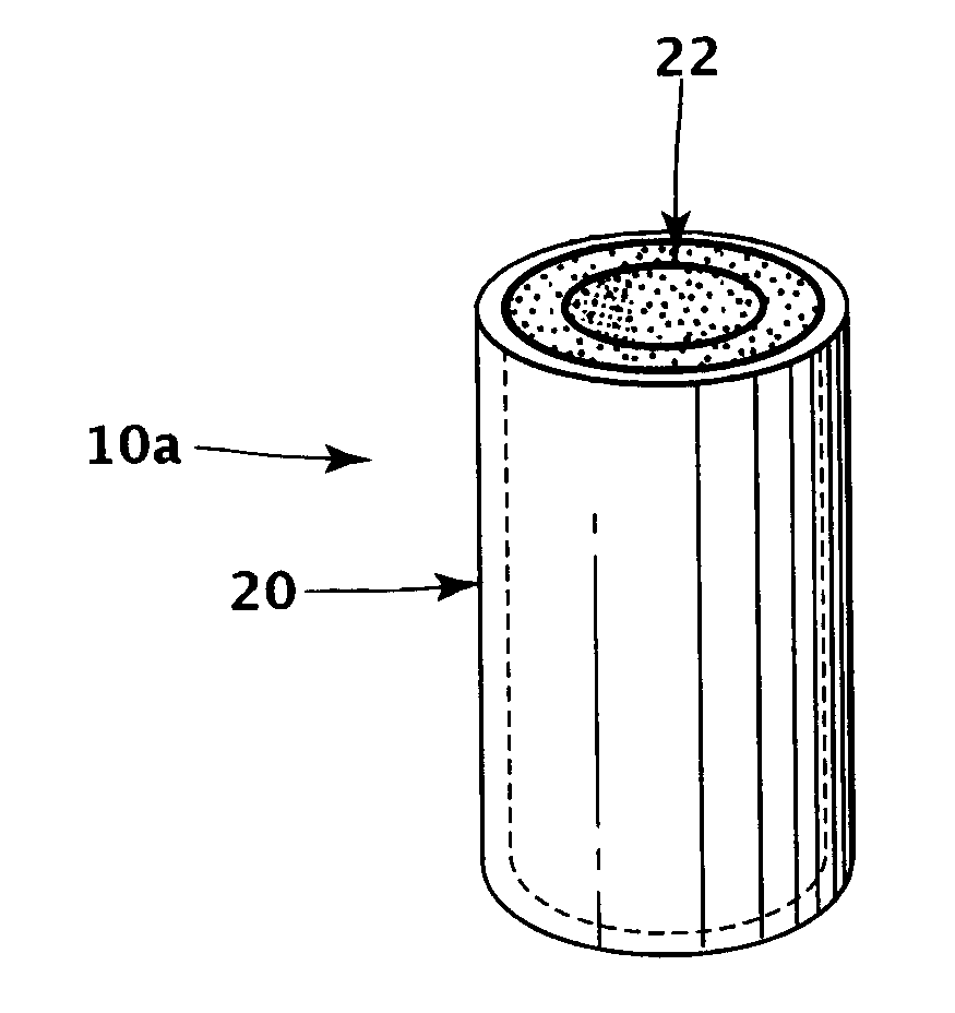
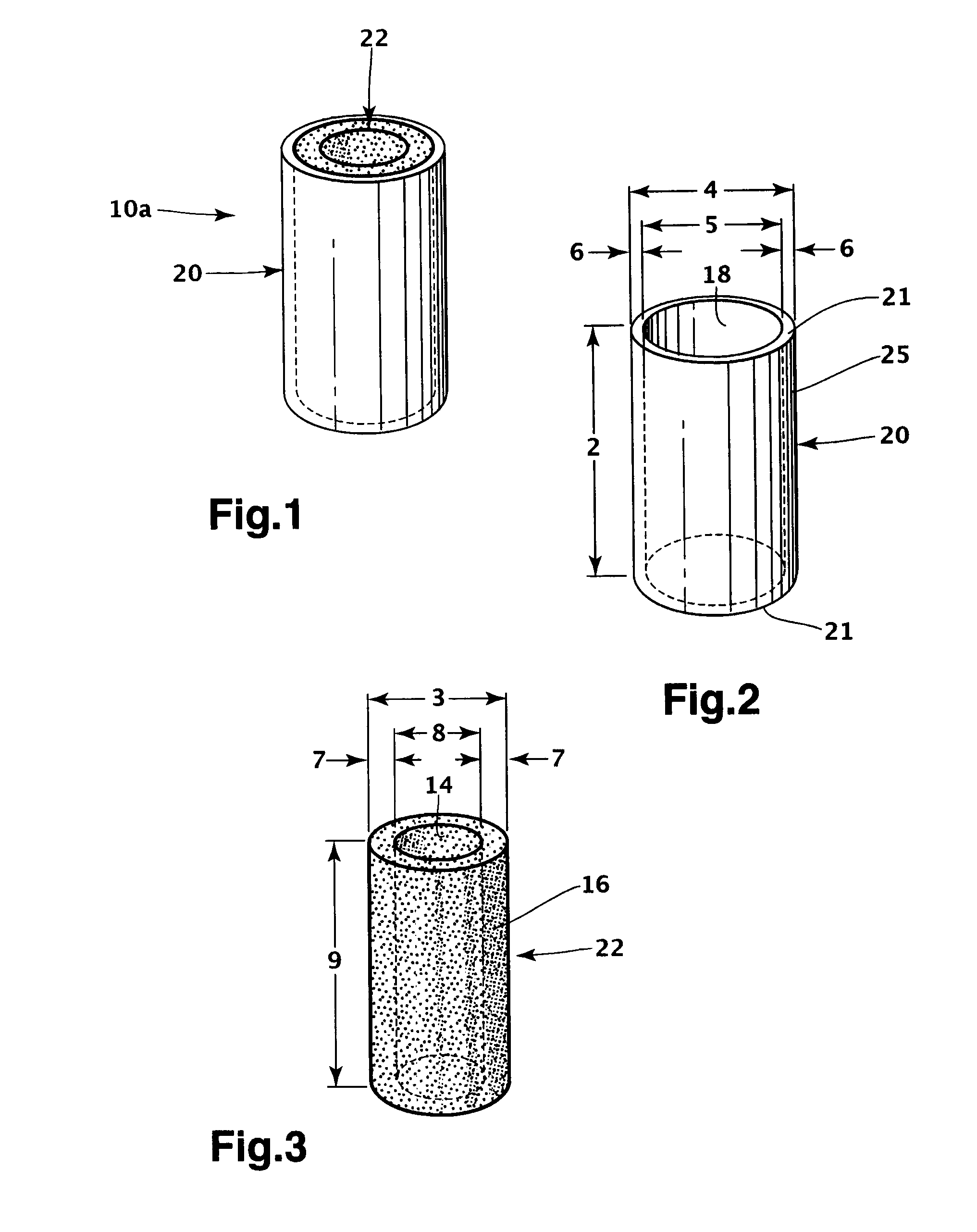
[0091]With respect to FIGS. 1 to 3, a metal tube with porous metal liner 10a will now be described. The metal tube with porous metal liner 10a (shown in FIG. 1) is a straight circular metal tube 20 having an inner wall 18 lined with a straight cylindrical metal foam liner 22. A method of obtaining such a tubular liner from a sheet of metal foam 30 will be described in greater detail below with reference to FIGS. 9 to 15. The metal foam liner 22 is metallurgically bonded in thermo-conduction with the metal tube 20. A method for making the metal tube with porous metal liner 10a will be described in greater detail below with reference to FIGS. 16 to 20.

[0092]As best seen in FIG. 2, the metal tube 20 has two open ends 21. It is contemplated that, for some applications, one end 21 would be closed (not shown), partially or totally. The metal tube 20 is made by extrusion and as a result has no seam. Although it is preferable that the metal tube 20 has no seam for applications such as heat ...

second embodiment

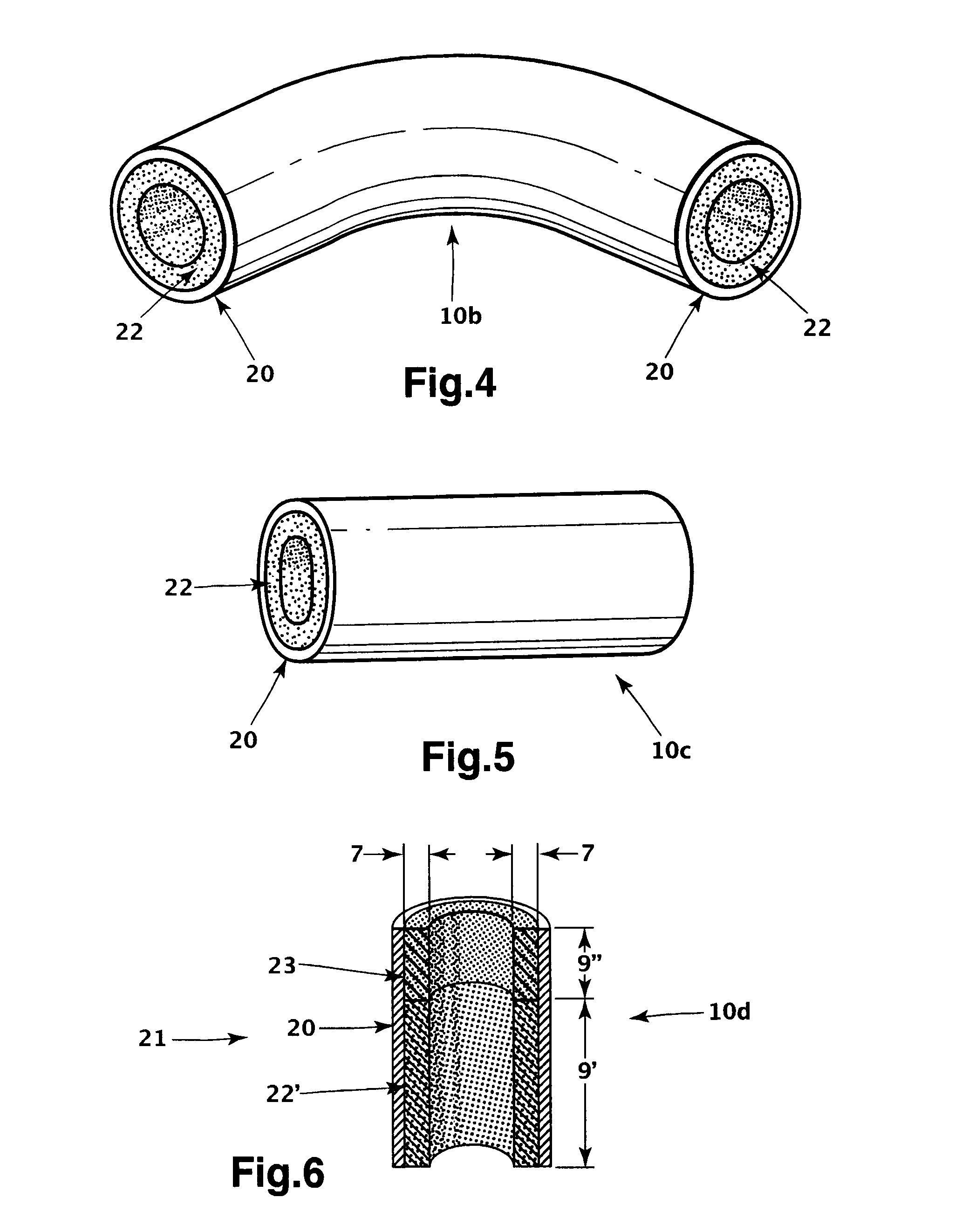
[0098]In a metal tube with porous metal liner 10b, shown in FIG. 4, the metal tube 20 and metal foam liner 22 are curved and form a curved metal tube with porous metal liner 10b. To obtain such a curved metal tube with porous metal liner 10b, one curves with conventional techniques the metal tube with porous metal liner 10b after the metal foam liner 22 has been inserted into and bonded to the metal tube 20. It is also possible to curve the metal tube with porous metal liner 10b after it has been transformed into a heat pipe.

third embodiment

[0099]In a metal tube with porous metal liner 10c, shown in FIG. 5, the metal tube with porous metal liner 10c has a flattened profile. To obtain such a flattened metal tube with porous metal liner 10c, one flattens with conventional techniques the metal tube with porous metal liner 10c after the metal foam liner 22 has been inserted into and bonded to the metal tube 20. It is also possible to flatten the metal tube with porous metal liner 10c after it has been transformed into a heat pipe.


PUM

PropertyMeasurementUnit
thicknessaaaaaaaaaa
thicknessaaaaaaaaaa
lengthaaaaaaaaaa

Abstract

A metal tube having an inner wall coated with a metal foam liner. The metal tube has an outer diameter of between 2 mm and 75 mm, a length of between 10 mm and 1000 mm, and a wall thickness of between 0.2 mm and 2 mm. The metal foam liner has a thickness of between 0.1 mm and 10 mm, a permeability of between 10−13 m2 and 10−8 m2, a capillarity radius of between 5 μm and 1 mm and a thermo-conductivity of between 1 W / m·K and 50 W / m·K. Also, a method to obtain a metal tube which inner wall is metallurgically bonded in thermo-conduction with a metal foam liner, a method to obtain a metal tube with a heterogeneous metal foam liner, and a method to obtain a tubular metal foam liner 10a from a sheet of metal foam.

Description

CROSS-REFERENCE[0001]The present application claims priority to U.S. Provisional Patent Application No. 61 / 154,752 filed Feb. 23, 2009 entitled “Metal Tube with Metal Foam Liner”, and to U.S. Provisional Patent Application No. 61 / 184,579 filed Jun. 5, 2009 entitled “Metal Tube with Heterogeneous Metal Liner”, the entireties of which are incorporated herein by reference.FIELD OF THE INVENTION[0002]The present invention relates to metal tubes having porous metallic liners therein serving as wicking structures, as well as to methods of making such tubes.BACKGROUND OF THE INVENTION[0003]In many applications, components need to be cooled so as to maintain their temperature within a range in which they can reliably operate. This is especially the case in the electronics industry where the power density of electronics is ever increasing while their enclosures are becoming ever smaller. Among the cooling solutions, heat pipes have found wide acceptance. Heat pipes have a flexible design and...

Claims


Application Information

Patent Timeline
Patent Type & Authority Applications(United States)
IPC IPC(8): F16L9/18B21D11/00B23K20/00
CPCB22F5/106B22F7/006F28D15/046F16L9/02B32B15/01
Inventor PILON, DOMINICLABBE, SEBASTIENSAVOIE, NOEMIE
Owner METAFOAM TECH INC
Why Eureka
Try Eureka