Method and apparatus for subband signal demodulation in a transponder satellite communication link containing a component of relayed interference

a technology of relay interference and subband signal, which is applied in the direction of pulse manipulation, pulse monitoring, pulse technique, etc., can solve the problems of significant degrading of subsequent interference reduction, power addition to channel noise at the receiver, and errors in parameter measurement, so as to achieve large cancellation factor and large cancellation factor

Active Publication Date: 2011-12-08
DATUM SYST
View PDF12 Cites 37 Cited by
  • Summary
  • Abstract
  • Description
  • Claims
  • Application Information

AI Technical Summary

Benefits of technology

[0013]The object of the invention is to provide a method and apparatus for demodulating a remote-terminal signal located in a frequency subband of relayed interference in a transponder satellite link. An additional object of the invention is to achieve and maintain a large cancellation factor of the freque...

Problems solved by technology

The cancelled relayed-interference signal is approximately complex Gaussian distributed so that its power adds to the channel noise at the receiver.
Errors in parameter measurement can significantly degrade the subsequent interference reduction.
However transferring the IF transmit signal requires a significantly larger bit transfer rate than transferring the digital data signal that produces the IF transmit signal resulting in a higher cost system.
Further, the Collins '641 and '104 patents and the Avellan '877 patent do not address the large dynamic range required and the limitation of cancellation caused by the presence of frequency-converter phase noise as discussed above....

Method used


Image

  • Method and apparatus for subband signal demodulation in a transponder satellite communication link containing a component of relayed interference
  • Method and apparatus for subband signal demodulation in a transponder satellite communication link containing a component of relayed interference
  • Method and apparatus for subband signal demodulation in a transponder satellite communication link containing a component of relayed interference

Examples


Embodiment Construction

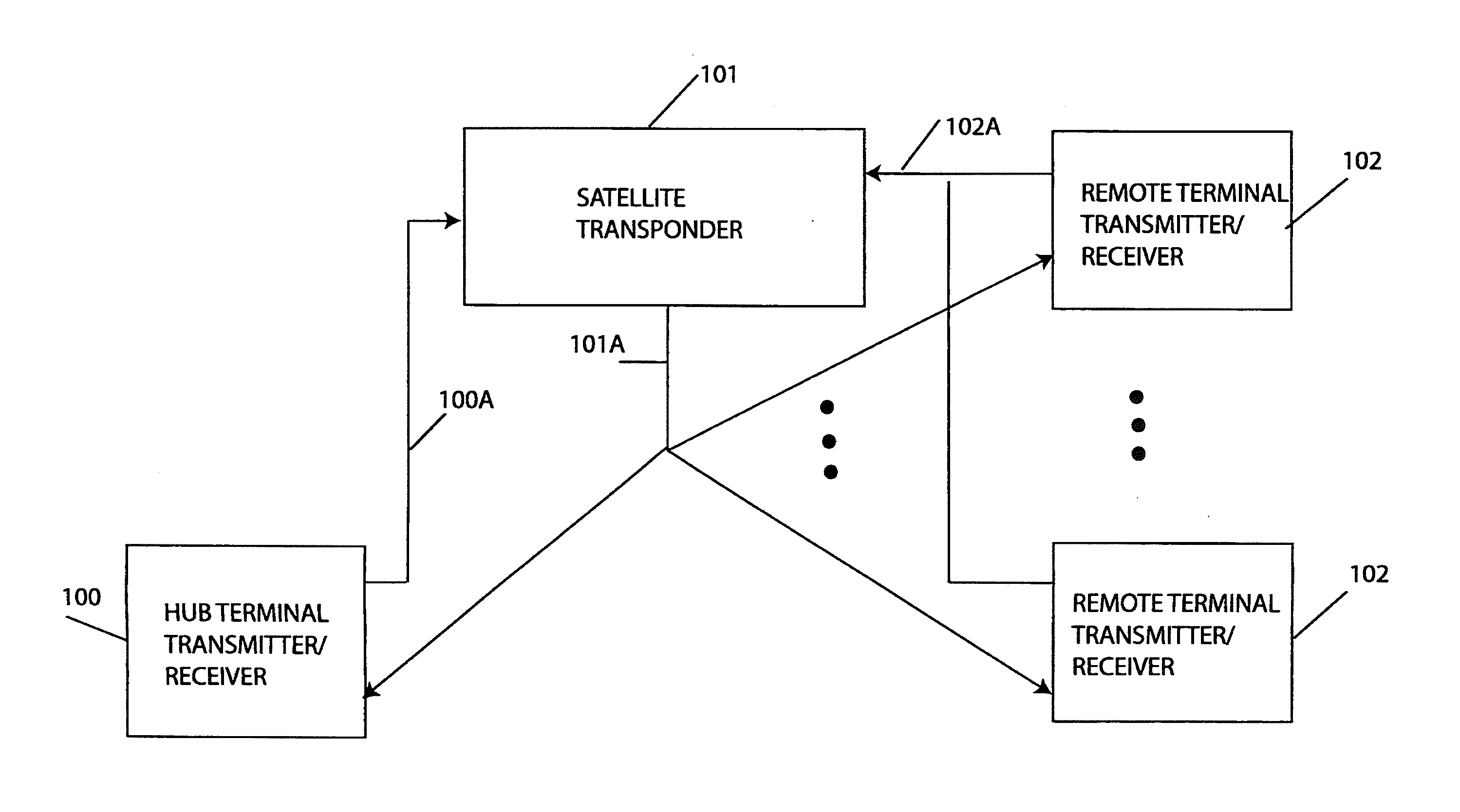
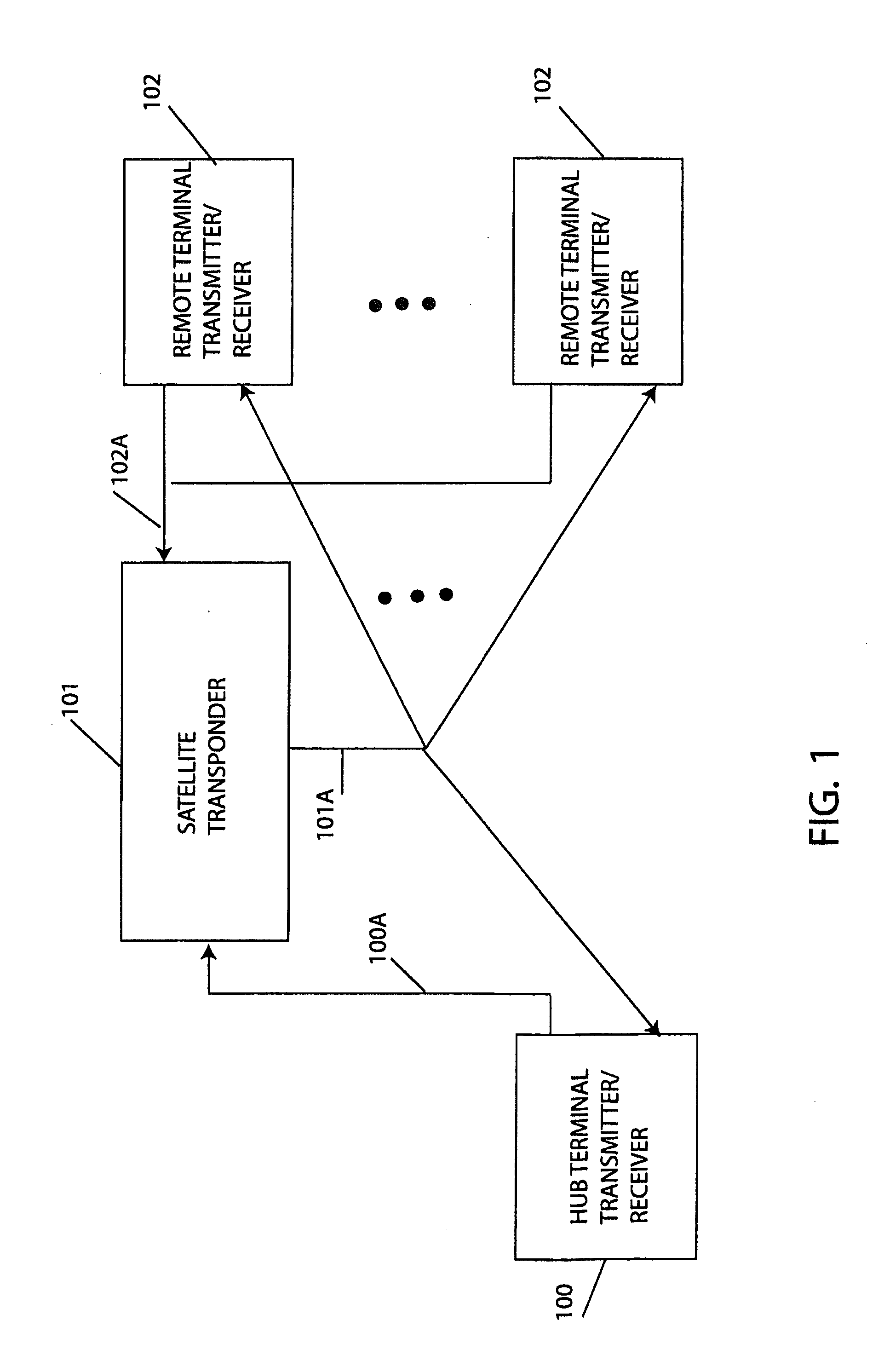
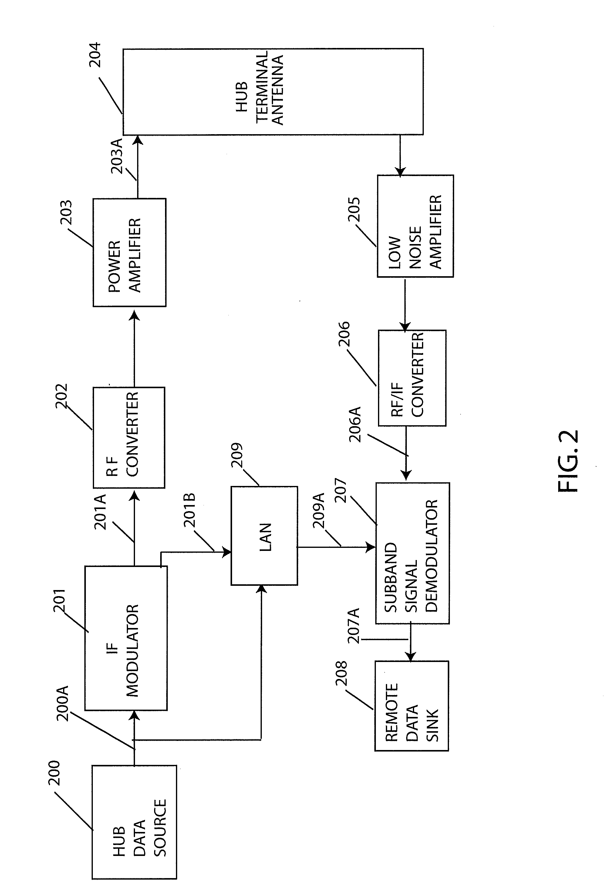
[0022]In the above prior art systems techniques the demodulation of a remote-terminal signal in a point-to-multipoint satellite application are not disclosed and the interference cancellation is broadband in that it includes all of the remote terminal signals in the bandwidth occupied by a wideband hub interference signal. The larger the bandwidth the more difficult it is to achieve a large interference cancellation (on the order of 45 dB) in the presence of link parameter variations. Consequently, a technique that performs the interference cancellation in the smaller bandwidth corresponding to the frequency subband of the remote-terminal signal has potential to provide improved interference discrimination. Further the technique of simultaneously performing interference cancellation and remote-terminal signal demodulation allows for the use of optimum filtering against noise to reduce dynamic range requirements and provide superior demodulation performance. This approach requires a ...


PUM


Abstract

A method and apparatus at a local terminal are described for demodulating a remote-terminal signal located at a subband offset frequency in a frequency subband of relayed interference from a transponder satellite link. The demodulation of the remote-terminal signal is accomplished by transferring the digital data that produced the local-terminal transmit signal to the local-terminal receiver. The digital data is time-delayed and converted to a narrowband offset-constellation signal that cancels the relayed interference in an adaptive equalizer. Providing cancellation in the subband of the relayed interference produces larger interference cancellation factors than those obtained in conventional broadband cancellation systems. A phase-noise error signal is also generated and used to increase cancellation levels limited by phase noise generated in the satellite link frequency converters. Additionally the receiver converter frequencies are chosen such that errors in estimating the subband offset frequency do not affect cancellation in the adaptive equalizer.

Description

CROSS-REFERENCE TO RELATED APPLICATION[0001]This application claims the benefit of copending application U.S. Provisional Application Ser. No. 61 / 343,951 filed on May 5, 2010, the disclosure of which is expressly incorporated herein by reference in its entirety.BACKGROUND OF THE INVENTION[0002]This invention relates to the demodulation of a remote-terminal signal in the presence of interference at a receiver in a local terminal of a point-to-multipoint radio communication link wherein the interference results from a subband component of a transmitted signal at the local terminal that has been relayed back to the local receiver by a satellite transponder link. The relayed-interference signal received at the local terminal is a result of effects on the transmitted signal by the satellite uplink to the transponder, the frequency translation and amplification in the transponder, and the satellite downlink back to the local terminal. These effects modify the transmitted signal to produce...

Claims


Application Information

Patent Timeline
IPC IPC(8): H04B7/185H04B17/00H04L27/01
CPCH04B7/18513H04L25/03019H04L2027/0065H04L2027/0053H04L27/0014
Inventor MONSEN, PETERBAGBY, DAVID
Owner DATUM SYST
Why Eureka
Try Eureka