Apparatus for Double-Sided, Grinding Machining of Flat Workpieces

a technology for grinding machining and workpieces, which is applied in the direction of flexible wheel, manufacturing tools, lapping machines, etc., can solve the problem that a large amount of burrs cannot even be formed in the first place, and achieve the effect of improving the deburring effect, facilitating further optimization of the deburring effect, and increasing flexibility

Inactive Publication Date: 2011-12-08
PETER WOLTERS GMBH
View PDF27 Cites 5 Cited by
  • Summary
  • Abstract
  • Description
  • Claims
  • Application Information

AI Technical Summary

Benefits of technology

[0017]According to another embodiment, the deburring means, in particular the deburring brushes, can be height-adjustable. This height adjustability can define exactly how far the deburring means can extend into the work gap. Moreover, a continuous readjustment of the position of the deburring means can be performed with the height adjustability if necessary, in order to maintain the desired projecting length even in the case of wear and tear of the deburring means. Normally, the wear of the deburring means takes place faster or slower than the wear of the grinding layers of the work disks. The height adjustment of the deburring means can for example take place through replaceable fixed or adjustable spacers, on which the deburring means, for example the deburring brushes are mounted. However, an adjustment is also conceivable by means of set screws, which can be actuated manually or by motor and permit height adjustment in this manner.
[0018]According to another embodiment, the deburring means can be driven in a rotating manner. The deburring effect is improved through rotation of the deburring means. The deburring means can thereby be driven by the same drive as the at least one work disk. But it is also conceivable to provide another separate drive than that of the work disk for the deburring means. This is conceivable in particular when the deburring means are arranged outside of the work disks and independently of them. In the case of this embodiment, the rotational speeds for the work disks and the deburring means can be selected independently of each other and opposite rotational directions can also be set for example. The flexibility is thereby increased and the deburring effect can be further optimized.

Problems solved by technology

Thus, a considerable amount of burrs cannot even form in the first place.

Method used


Image

  • Apparatus for Double-Sided, Grinding Machining of Flat Workpieces
  • Apparatus for Double-Sided, Grinding Machining of Flat Workpieces
  • Apparatus for Double-Sided, Grinding Machining of Flat Workpieces

Examples


Embodiment Construction

[0027]While this invention may be embodied in many different forms, there are described in detail herein a specific preferred embodiment of the invention. This description is an exemplification of the principles of the invention and is not intended to limit the invention to the particular embodiment illustrated

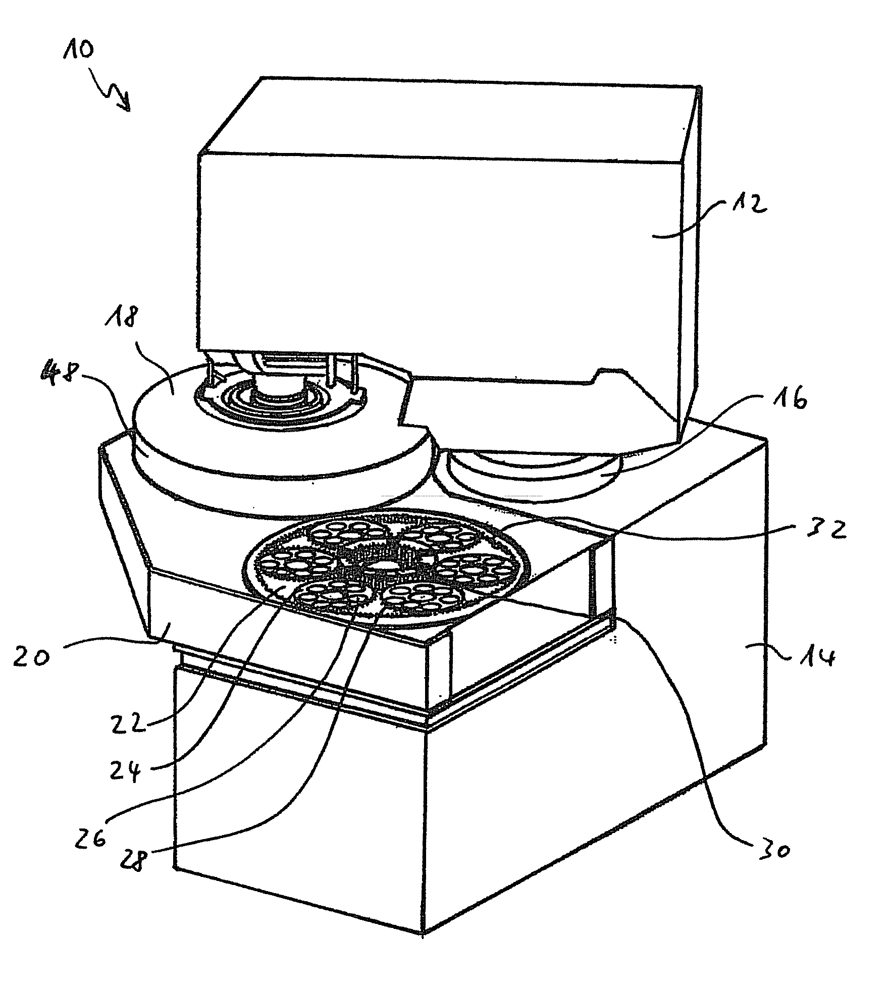
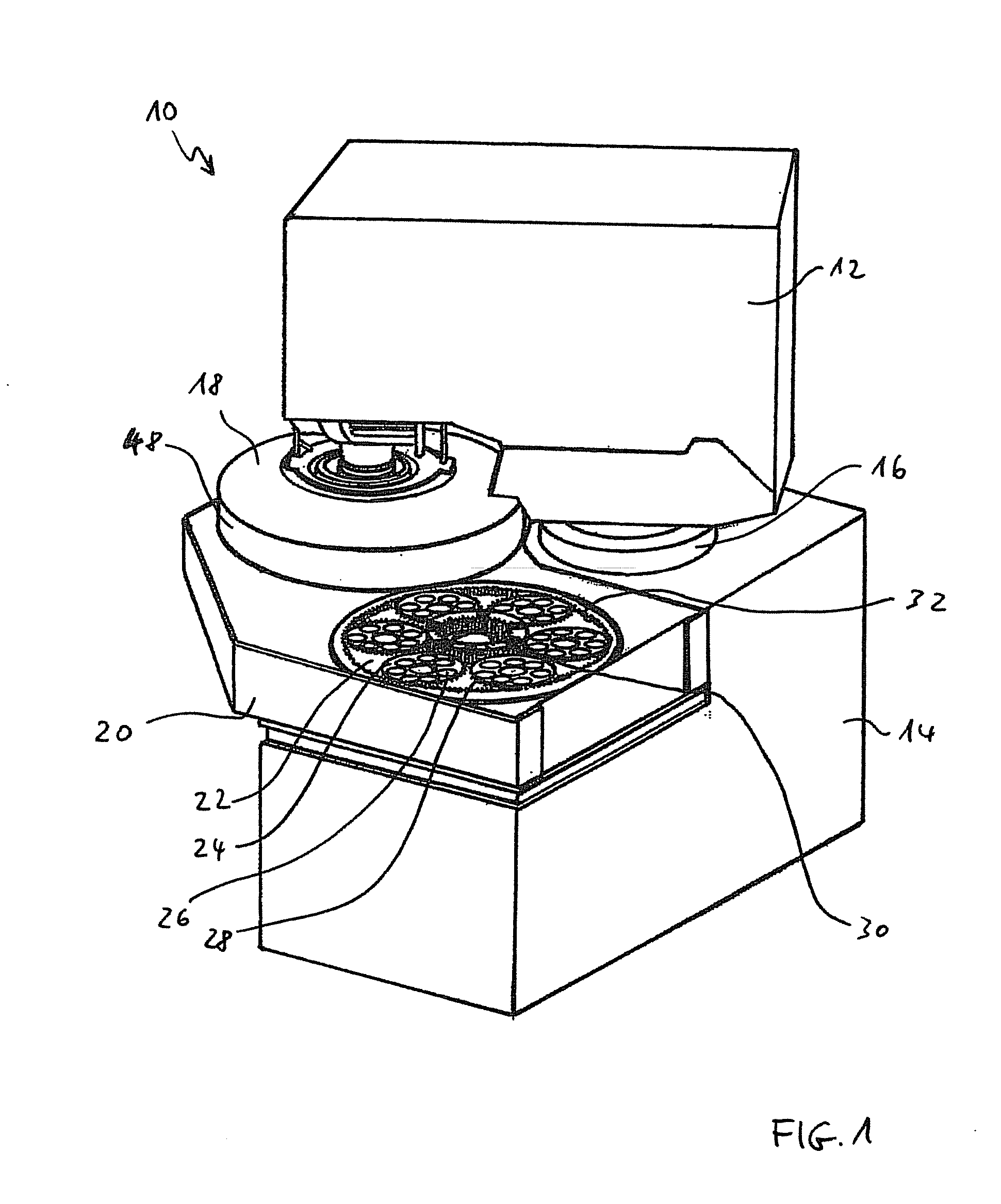
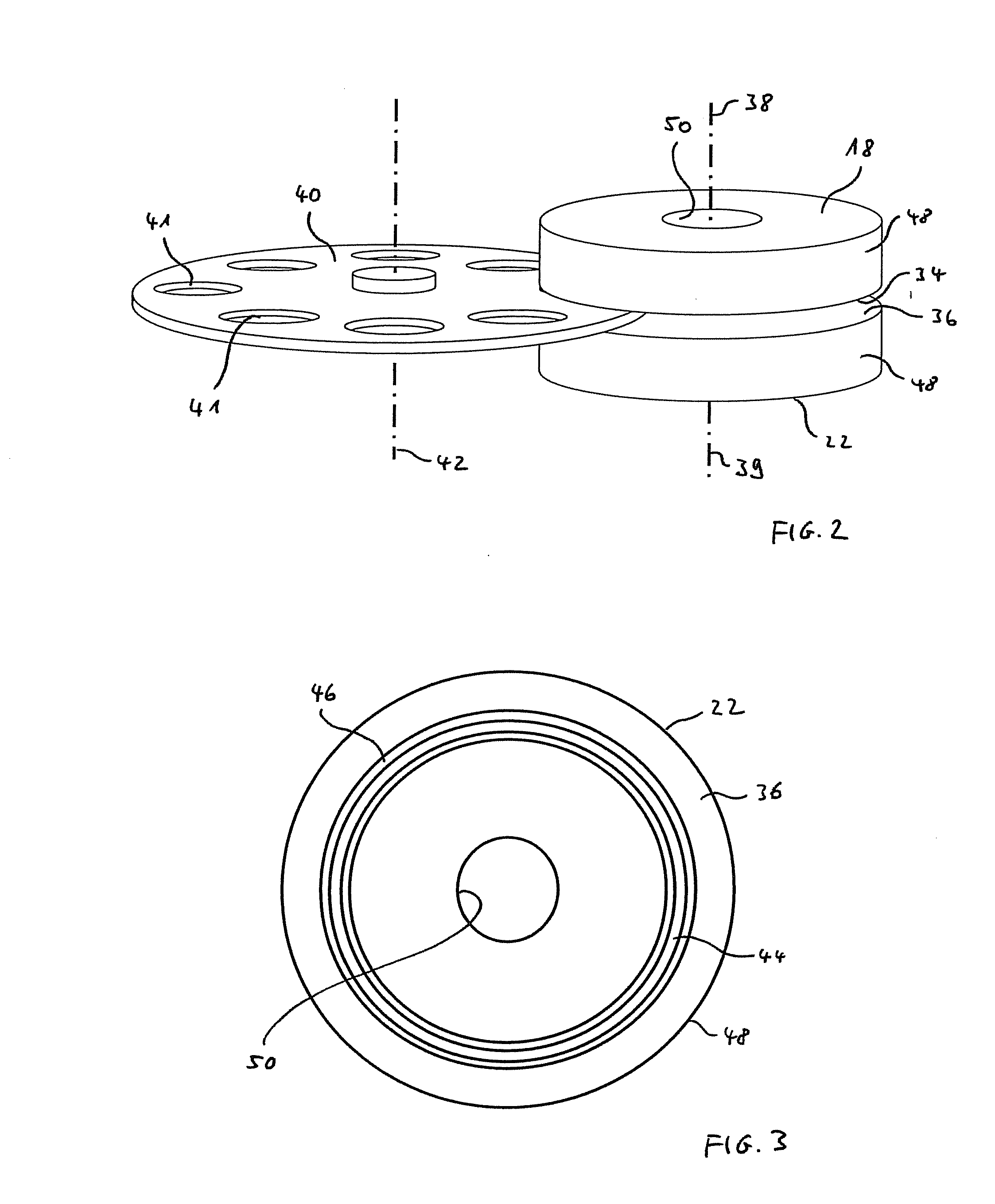
[0028]If not specified otherwise, the same reference numbers are used for the same objects in the figures. FIG. 1 shows the general structure of an apparatus according to the invention for double-sided machining of flat workpieces. The apparatus shown in the example in FIG. 1 is a double-side grinding machine 10 with planetary kinematics. The apparatus 10 has an upper pivot arm 12, which can be pivoted around a vertical axis via a pivot device 16 mounted on a bottom base 14. An annular upper work disk 18 is carried on the pivot arm 12. The upper work disk 18 is rotatably drivable via a drive motor not shown in greater detail in FIG. 1. On the bottom side not shown in FIG. 1, t...


PUM


Abstract

The invention relates to an apparatus for the double-sided, grinding machining of flat workpieces with an upper and a lower work disk, each of which has a work surface with a grinding layer, wherein the work surfaces form a work gap amongst themselves, in which workpieces can be ground, wherein at least one of the work disks is rotatably drivable by means of a driving mechanism, and further having a device for guiding the workpieces in the work gap. It is provided according to the invention that debarring means are arranged on at least one of the work disks, which are designed to deburr the workpieces during their machining in the apparatus.

Description

CROSS-REFERENCE TO RELATED APPLICATIONS[0001]Not applicable.[0002]STATEMENT REGARDING FEDERALLY SPONSORED RESEARCH[0003]Not applicable.BACKGROUND OF THE INVENTION[0004]The invention relates to an apparatus for the double-sided, grinding machining of flat workpieces with an upper and a lower work disk, each of which has a work surface with a grinding layer, wherein the work surfaces form a work gap amongst themselves, in which workpieces can be ground, wherein at least one of the work disks is rotatably drivable by means of a driving mechanism, and further having a device for guiding the workpieces in the work gap.[0005]The use of double-side, surface-grinding machines for precise machining of workpieces with two plane-parallel surfaces is known. There are many corresponding machines with different designs. All conventional double-side, surface-grinding machines are similar in that they have two, normally annular work disks, the front surfaces of which are covered with an abrasive ma...

Claims


Application Information

Patent Timeline
Patent Type & Authority Applications(United States)
IPC IPC(8): B24B7/00B24B37/08
CPCB24B29/005B24B9/00B24B37/08B24D13/145B24B7/17B24B7/228
Inventor FRIES, ADRIAN
Owner PETER WOLTERS GMBH
Why Eureka
Try Eureka