Removable wear-plate assembly for acoustic probes

a technology of wear-plate assembly and acoustic probe, which is applied in the direction of fluid pressure measurement, instruments, magnetic property measurement, etc., can solve the problems of expensive repair or replacement, premature wear of the probe contact surface, and loss of time, and achieve the effect of desirable acoustic performan

Active Publication Date: 2011-12-15
OLYMPUS AMERICA
View PDF7 Cites 30 Cited by
  • Summary
  • Abstract
  • Description
  • Claims
  • Application Information

AI Technical Summary

Benefits of technology

[0013]The invention disclosed herein avoids or ameliorates the aforementioned drawbacks and problems related to the protective layer or wear plates of ultrasonic probes used in NDT / NDI devices, where existing wear protective measures either lack the sufficient protection for the probes from being wrung against test object, or the desirable acoustic performance, or operation efficiency.

Problems solved by technology

The movement with force against rough, hard, and abrasive test object surfaces causes damage and premature wear of the probe contact surface.
Severely worn or damaged probes require expensive repair or replacement and result in lost time.
Existing effort and means for protecting probes from damage and wear are known but present limitations of various kinds.
In addition, even hard plates eventually wear thin, particularly the perimeter of the hard plate and any portion of the probe housing near the perimeter are further subject to wearing forces greater than the central, planar surface of the plate.
In addition, housing corners and brittle, thin, plate edges forcibly moved against surface protrusions may chip and break away, accelerating probe wear and damage.
Bonded hard wear plates are not easily separated from other probe structures, making repair or replacement of damaged or worn parts difficult or not possible.
The provided protection of hard plates is therefore limited by the wear of the plates, and the difficulty of repair or replacement.
These probes are not designed to be directly in contact with metal test objects as the relatively soft plastic face would wear out quickly when wrung against rough metal surfaces.
However, these integral, plastic-like, protective face layers do not provide sufficient protection to the probes.
However, the plastic-like, soft-face layers are generally vulnerable to wear.
In addition, array probes have high replacement cost.
The use of plastic delay lines and refracting wedges, however, introduces an array of issues from increased operation complexity, to the impact of measurement accuracy and to noises introduced in the volume of the plastic accessories.
However, plastic and rubber like materials may not slide in a smoothly scanning motion because they plastically deform into the interstices of work surface asperities and increase friction.
A further problem with thin plastic plates and flexible membranes is that they may be penetrated by relatively large and sharp, work surface protrusions and fail to adequately protect the probe.
Thick layers would provide greater protection but degrade the range of inspection.
In addition, in both cases of thin and thick plastic protective surfaces, delay-line multiple echoes presents problems for inspections.
Equipment for containment, re-circulation and replenishment may be costly and cumbersome or impractical to use at the inspection site.
However, the standoff devices may not adequately protect probes from work surface protrusions that are larger than the standoff distance, which could often happen.
Delay line multiple echoes that occur prior to or coincident with signal echoes from within the test object can interfere with signal interpretation and cause measurement inaccuracies.
The practical inspection range is usually limited by the travel time within the delay line.
Longer delays have longer delay times, but attenuation and sound beam spread increases with length.
Attenuation reduces signal strength and causes frequency distortions of the signal.
Beam spread reduces signal strength and causes additional noise echoes when the spreading beam reflects from the side of the delay line.
Although thick delay lines and long water columns can provide good protection for probes, they limit the inspection range.

Method used


Image

  • Removable wear-plate assembly for acoustic probes
  • Removable wear-plate assembly for acoustic probes
  • Removable wear-plate assembly for acoustic probes

Examples


Embodiment Construction

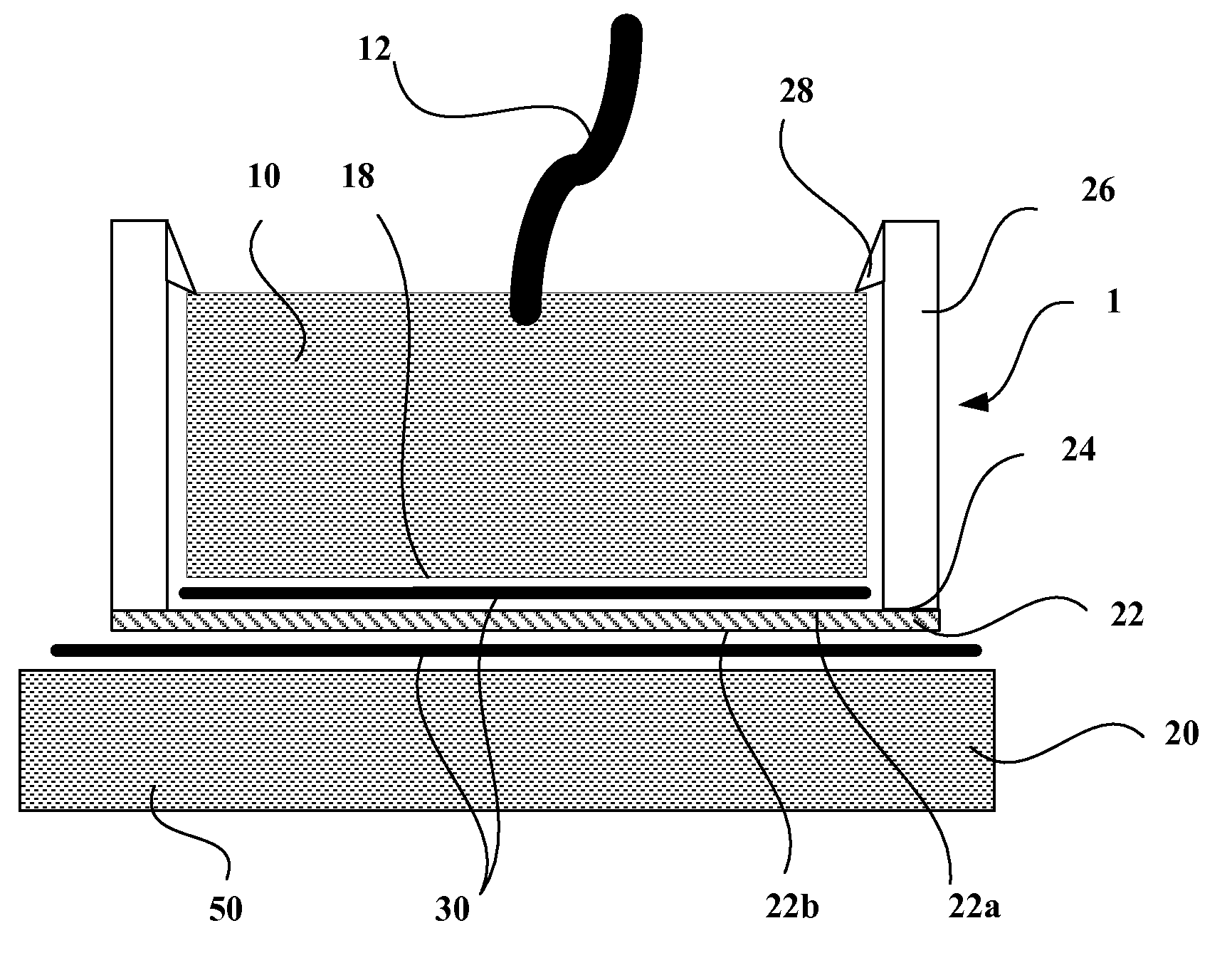
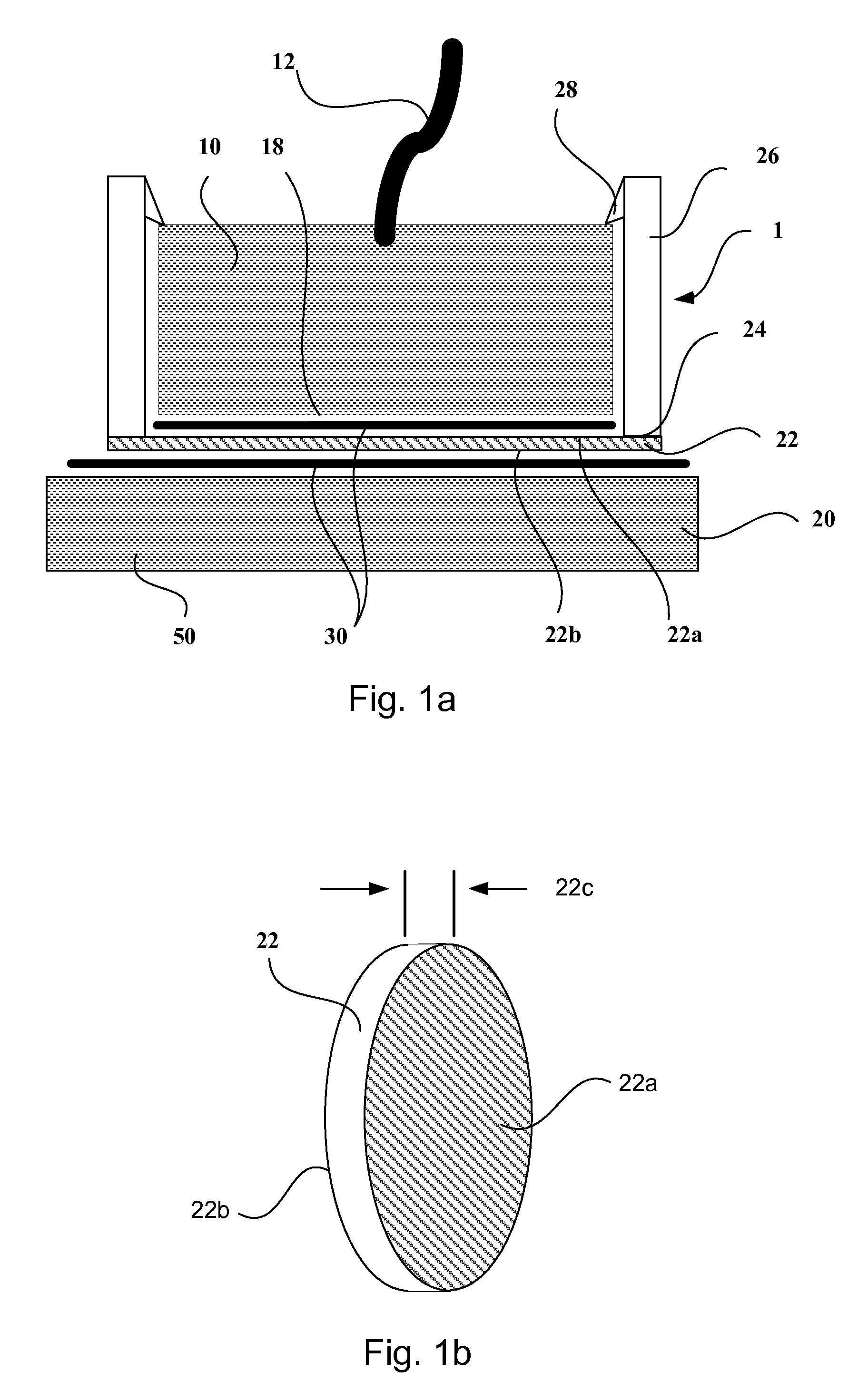
[0029]Referring to FIG. 1a, a preferred embodiment of an ultrasonic probe 1 according to the present invention is shown. This preferred embodiment is chosen to illustrate herein disclosed ultrasonic probe assembly 1 and is not meant to place any restriction on the scope and variations of the invention.

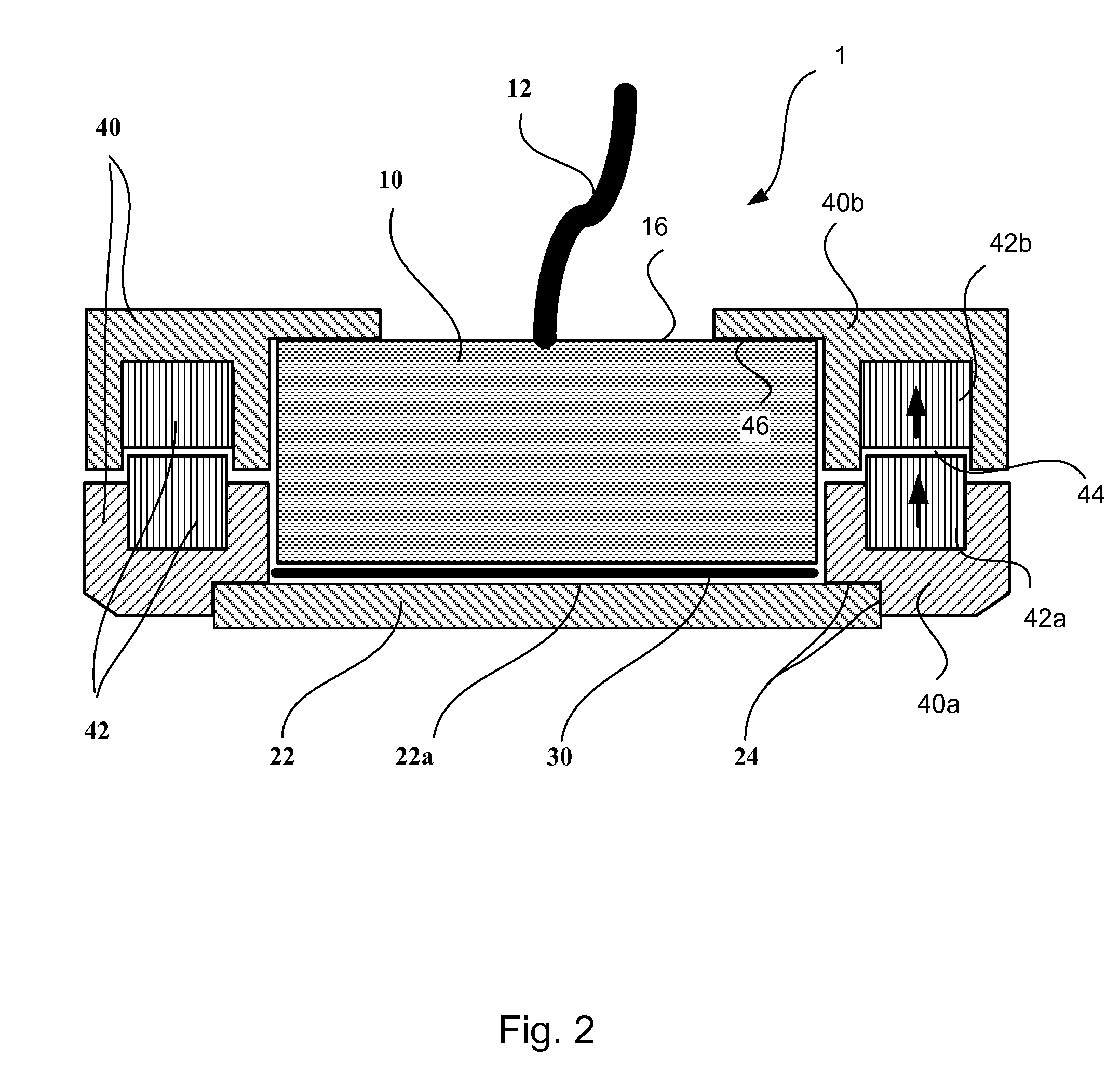
[0030]As shown in FIG. 1a, probe assembly 1 comprises an ultrasonic probe 10, a probe cable 12, a removable wear plate 22, a wear plate holder 26 and a layer of liquid couplant 30.

[0031]Probe assembly 1, during an inspection operation, is placed on and moved over the surface of a test object 20 to inspect object 20. During the operation, wear plate 22 comes into contact with test object 20 via fluid coupling 30.

[0032]Plate holder 26 preferably further comprises a fastening clip 28 to hold probe 10 to be contained within plate holder 26. Wear plate 22, wear plate holder 26 and fastening clip 28 together forms a housing for probe 10, and are configured to protect probe 10 during operatio...


PUM

PropertyMeasurementUnit
flexural strengthaaaaaaaaaa
tensile strengthaaaaaaaaaa

Abstract

Disclosed is a wear plate assembly for NDT/NDI probes which provides sufficient protection for the probe being wrung against test objects, desirable acoustic performance meeting the requirements for versatile ultrasonic inspections while providing a mechanism that allows the transducer to be put into or taken out conveniently. The wear plate protects probes from being pieced, worn or structurally deformed albeit being thinner than a wavelength of the acoustic echoes.

Description

FIELD OF THE INVENTION[0001]The present invention relates to an acoustic probe and probe accessory associated with non-destructive testing and inspection (NDT / NDI), more specifically to a removable covering assembly for preventing wear and damage to the probe that is used in contact with NDT / NDI test objects without introducing undesirable acoustic delay.BACKGROUND OF THE INVENTION[0002]Acoustic / ultrasonic probes used for contact inspections are wrung against and moved on test object surfaces. The wringing movement improves the signal by removing excess coupling liquid or gel from between the probe and the work surface. Probes are also moved on the surface to locate features or examine adjacent areas of the test object. The movement with force against rough, hard, and abrasive test object surfaces causes damage and premature wear of the probe contact surface. Severely worn or damaged probes require expensive repair or replacement and result in lost time.[0003]The need for protective...

Claims


Application Information

Patent Timeline
Patent Type & Authority Applications(United States)
IPC IPC(8): G01N29/00G01D11/24
CPCG01N29/28G01D11/245
Inventor KASS, DANIEL STEPHENSTANTON, MATTHEW EDWARDNELLIGAN, THOMAS J.
Owner OLYMPUS AMERICA
Why Eureka
Try Eureka