Lower emergency marine riser(LEMR) and method of installation preventing catastrophic product spills

a technology of emergency riser and product, which is applied in the direction of drilling pipes, drilling well accessories, sealing/packing, etc., can solve the problems of many backup systems in place, few means of controlling the disastrous and uncontrolled output of oil, and many failures of products from the sea floor. , to achieve the effect of quick replacement of failed bops, easy installation and convenient manufactur

Inactive Publication Date: 2011-12-15
HERMAN II JOHN WAYNE
View PDF3 Cites 29 Cited by
  • Summary
  • Abstract
  • Description
  • Claims
  • Application Information

AI Technical Summary

Benefits of technology

[0015]MY Lower Emergency Marine Riser (LEMR) (pronounced leaner') is a unique and easily manufactured attachment for an LMRP.
[0016]It is easily mounted and can quickly replace a failed BOP almost immediately, when on hand.
[0017]My unique LEMR can get production going full steam ahead, almost immediately.
[0018]No relief wells or other costly equipment would ever be necessary.
[0019]My LEMR will have little impact on production flow rate.
[0020]I believe a LEMR must be manufactured for every well on the globe, so that in the event of a similar disaster, it would be ready for immediate deployment, so that spillage would be at the absolute minimum and the impact to the environment minimized. The value of my invention is immeasurably evident. Moratoriums could be lifted. More exploration unhindered, since a viable method with such rapid solution to any similar catastrophe would be averted.

Problems solved by technology

Recent events, such as the Deepwater Horizon disaster, lead to unsuccessful means of stopping the flow of product from the sea floor due to a failure of the BOP (Blow Out Preventer) which has been one of the primary ways to control a blowout, but not many backup systems are in place, which is now evident.
Not only are there seemingly few means for controlling a disastrous and uncontrolled output of oil, but all the methods previously used to stop the uncontrolled oil flow as well as capturing the oil has failed as well.
Most all prior art and patents cover only new drilling applications and well drilling methods or devices to that end, but very few, if any, emergency devices have been developed for failure of the BOP, for example, or failure of the entire Lower Marine Riser Package (LMRP) and other system devices or complete loss of the drilling platform, which upon its tragic demise, could impede access to the LMRP.
Recent attempts of top killing by pumping heavy mud and other drilling fluid in the LMRP and BOP mechanism have failed.
A Riser Insertion Tool was an ineffective contingency for capture with minimal results.
Initially, many days were lost and great spillage occurred while construction of a containment dome was scrapped for impractical reasons and complications.
Drilling relief wells is time consuming and does not immediately stop the uncontrolled flow of product escaping into the environment from the damaged LMRP.
Other attempts to recover the uncontainable product, was to use a LMRP Top Hat Cap which captured some small amount of oil and the insertion of a suction tube has produced ineffective results as well.
Not one of the above utilized solutions can get the well system back to prime operating condition.
It appears most patents do not address emergency contingencies like Deepwater Horizon and have similar disadvantages.
While some stop product flow, they cannot get the production going again without loss of product.
Again its, disadvantage is that it cannot get the well back into immediate and FULL production, perhaps within 24 hours of the disaster as my invention can do.
Their major disadvantages are that they seal the well with no opportunity for immediate restoration of production and recovery of product and full production flow.
In the case of the recent disaster, these devices, or other similar devices, have a risk of failing.

Method used


Image

  • Lower emergency marine riser(LEMR) and method of installation preventing catastrophic product spills
  • Lower emergency marine riser(LEMR) and method of installation preventing catastrophic product spills
  • Lower emergency marine riser(LEMR) and method of installation preventing catastrophic product spills

Examples


Embodiment Construction

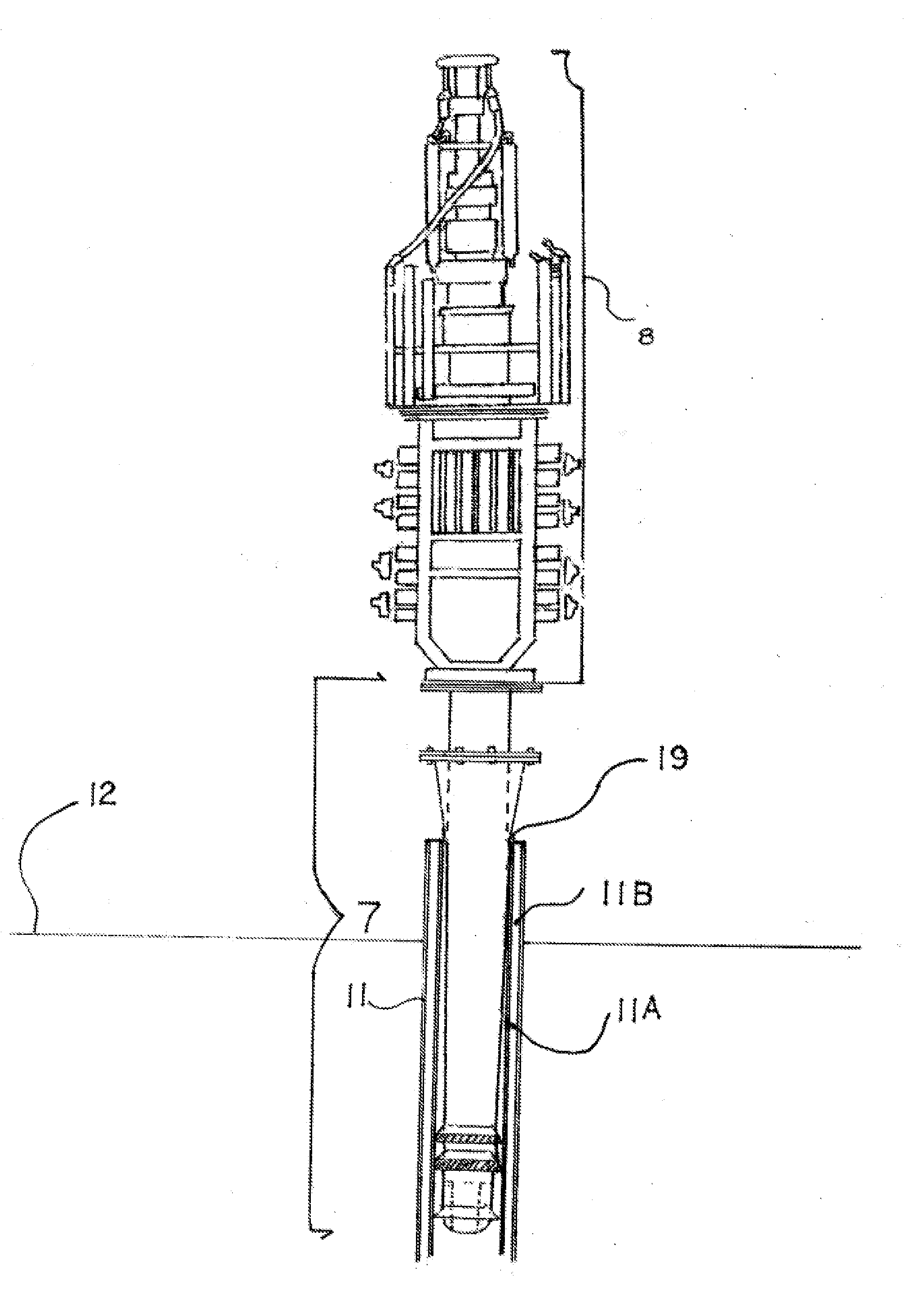
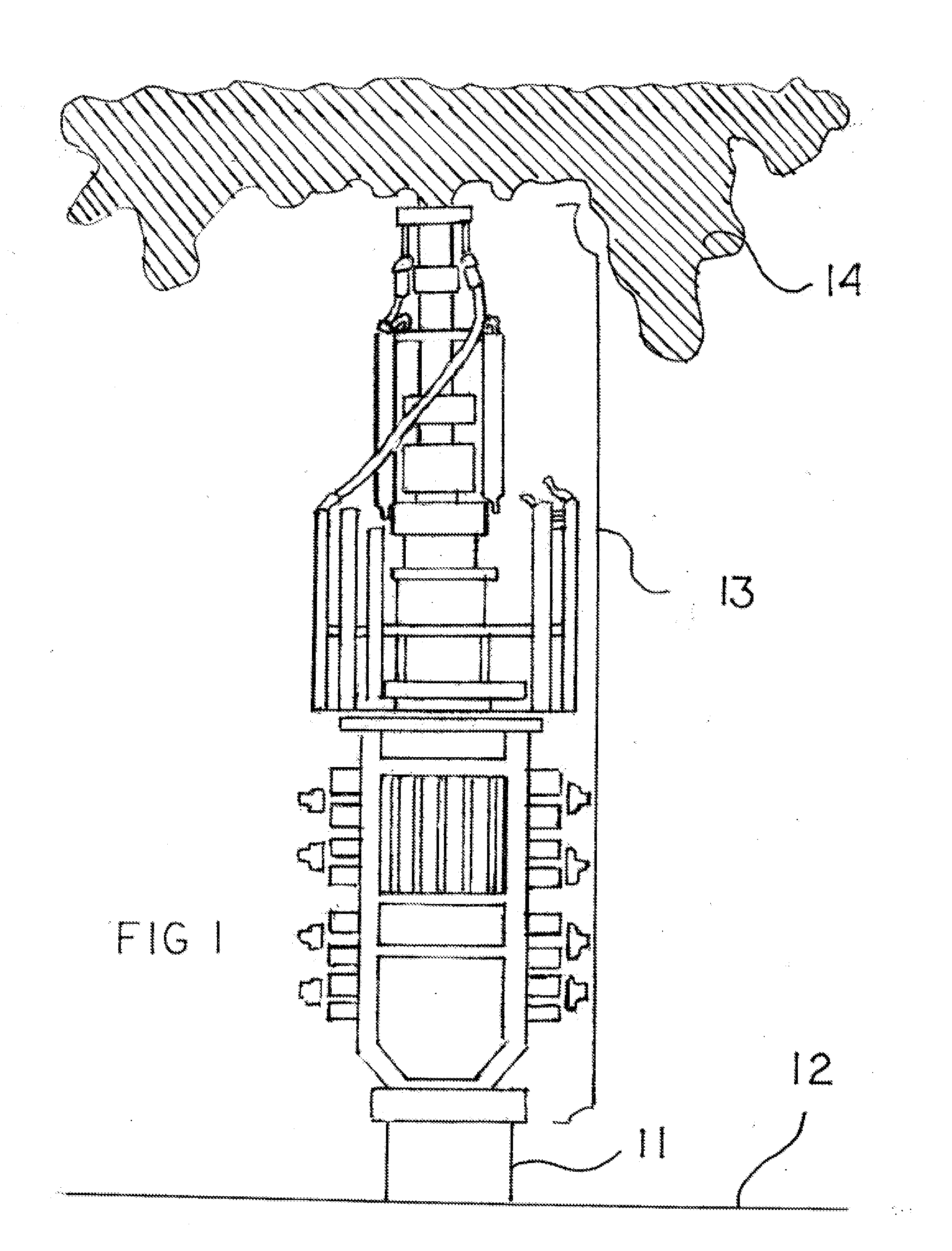
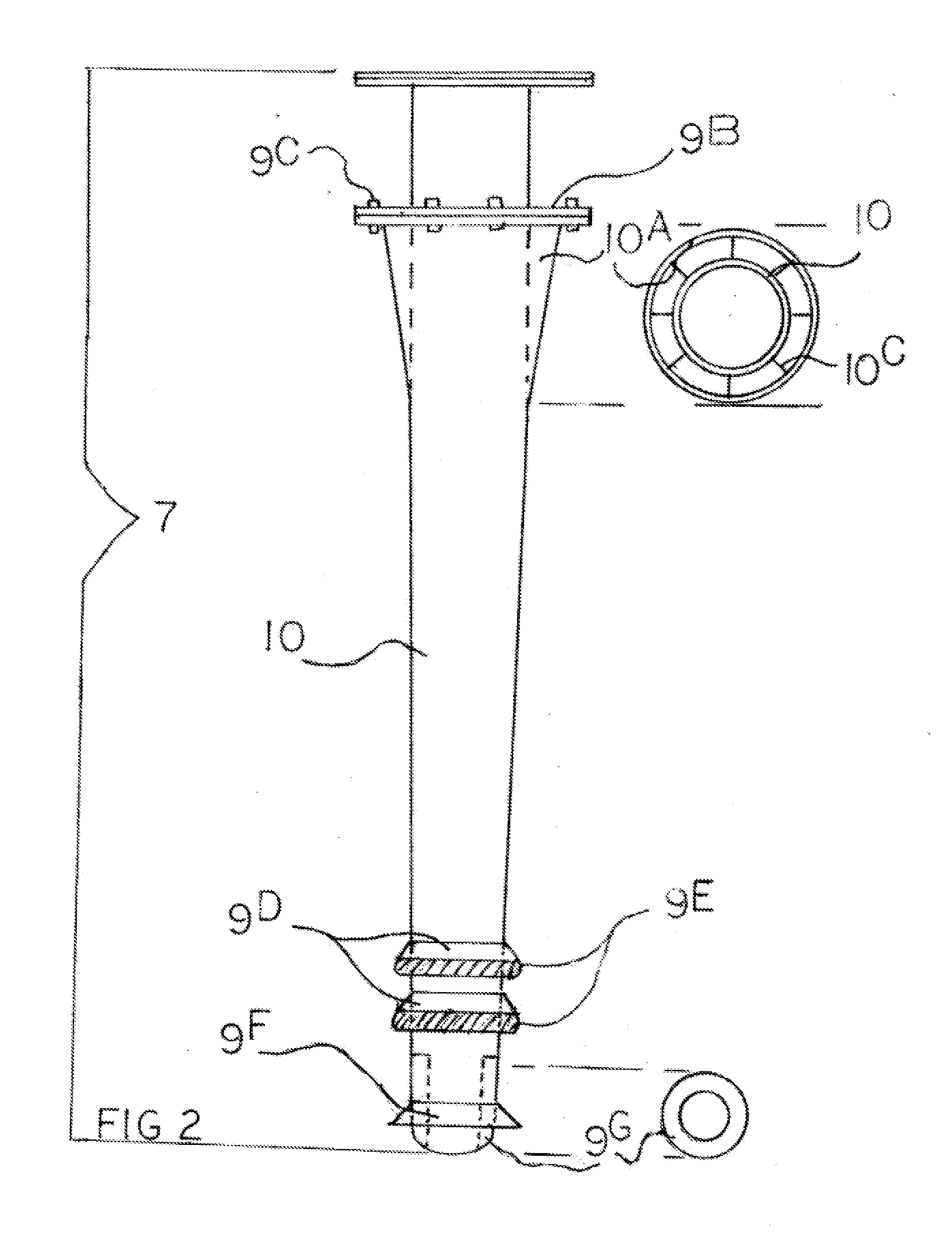
[0029]Illustrated in FIG. 1, is the now infamous defective Blow Out Preventer (BOP) found within a Lower Marine Riser Package (LMRP) 13 is connected to the wellhead 11 on the seafloor 12 as product 14 uncontrollably spills into the gulf. My unique Lower Emergency Marine Riser or LEMR 7 attaches to the base of the LMRP 8. LEMR is comprised of a specialized conduit or metal piping 10 having an upper coupling or flange 9A to connect to a LMRP, normally where the LMRP would be directly slipped over a wellhead 11 and can be welded as a slip in coupling or bolted with the flange 9A. Just below the coupling or flange 9A is an emergency rapidly disconnecting connector or flange 9B having explosive bolts 9C or other quick disconnecting application. Just under the backup flange 9B is a tapered shroud 10A which is a large, reinforced downwardly exaggerated, and somewhat elongated tapered cone of sorts, welded just under the emergency flange 9B and wraps around the upper portion of the speciali...


PUM


Abstract

A specialized conduit 10 of undetermined length with an emergency disconnecting flange or coupling 9B as well as lower flared fittings and O-rings at the lower end of specialized conduit: a) for sealing conduit to wellhead casing liner and b) cleaning wellhead casing liner during entry and said specialized conduit has an upper reinforced tapered shroud over the specialized conduit that when inserted into wellhead casing liner creates a tight metal to metal seal and said specialized conduit tip is reinforced with a machined stainless steel nose piece and upper end of specialized conduit is fitted or formed with coupling or bolt flange to attach to a new LMRP, creating a Lower Emergency Marine Riser (LEMR) to insert into a wellhead for rapid replacement of defective BOP creating immediate and uninterrupted well production and simultaneous containment.

Description

BACKGROUND[0001]1. Field of Invention[0002]This invention relates to well drilling and the proven possibilities of defective equipment which has been known to cause uncontrolled environmentally catastrophic spillage of product, to thereby provide a rapidly manufactured solution for assembly onto a well system control device, for the means to quickly stop catastrophic and uncontrolled output, thereby rapidly restoring product extraction as needed and should be manufactured as an on-hand emergency contingency for every well on the globe, for use in future or present disasters, whether great or small, as a quick containment resolution, eliminating the need for pressure relief wells and other costly and unsuccessful methods of stopping uncontrolled output, utilizing a tremendous cost savings to the industry, while preventing future hazardous impact on the environment, enabling further exploration with this safety feature and my invention is the only solution.[0003]2. Description of Prio...

Claims


Application Information

Patent Timeline
Patent Type & Authority Applications(United States)
IPC IPC(8): E21B17/01
CPCE21B43/0122E21B33/038
Inventor HERMAN, II, JOHN WAYNE
Owner HERMAN II JOHN WAYNE
Why Eureka
Try Eureka