Iris-shaped variable valve

a variable valve and valve body technology, applied in the field of valves, can solve the problems of large pressure loss, aggravate exhaust noise, complicated control system, etc., and achieve the effect of reducing pressure loss and flow noise, and easily forming a flow rate or pressure control system

Inactive Publication Date: 2011-12-15
LEE KEUN SANG
View PDF12 Cites 9 Cited by
  • Summary
  • Abstract
  • Description
  • Claims
  • Application Information

AI Technical Summary

Benefits of technology

[0014]The aperture-shaped variable valve according to the present invention may control the flow rate or back pressure linearly and reduce the pressure loss and flow noise, compared to a conventional disc variable valve.
[0015]The aperture-shaped variable valve according to the present invention may be attached to the inside or end of the pipe to variably control the flow pressure of fluid changing the flow rate at any time and flowing along the pipe.
[0016]The aperture-shaped variable valve according to the present invention may use a simple actuator performing a rectilinear movement to adjust an opening area of the valve as the discharger area by various tools and methods and to easily form a flow rate or pressure control system.

Problems solved by technology

Also, the shape of the flow path inside the valve drastically changes to fluctuate the velocity and pressure of fluid to thereby cause a turbulent flow, resulting in great pressure loss, flow noise and vibration.
To control the typical valves as above, an additional motor is required to rotate the rotation part of the valves and the control system becomes complicated.
Automotive muffler is used to reduce exhaust noise by gradually decreasing the pressure of exhaust gas since high temperature and high pressure pulsating exhaust gas causes great noise due to a drastic change in pressure if being emitted to the atmosphere as is.
By contrast, if the exhaust resistance is reduced to prevent the power loss of the engine, the exhaust noise aggravates.
However, in the case of a conventional disc variable valve, an opening area does not linearly increase according to an opening angle of the disc and it is very difficult to calculate the flow rate which is discharged through the opening area.
Thus, it is not easy to manufacture an appropriate variable valve, and the common application of manufactured variable valves to other mufflers is limited.
In the case of the disc variable valve, opening the valve makes the flow path very complicated, and the flow of the fluid drastically changes, and causes noise and vibration due to a turbulent flow.
To that respect, the variable valve may reduce the pulsating noise from the engine, but the flow noise from the variable valve increases, and the overall improvement for the exhaust noise is not that great or may become worse.
Conventional flowmeters which measure the flow rate through a differential pressure by using a ventury tube or nozzle has its cross sectional area fixed to measure the differential pressure, and are not appropriate for measuring a wide range of flow rates.
In the former case, the flowmeters cannot be used adjacently in a desired location due to an interference of the flow.

Method used


Image

  • Iris-shaped variable valve
  • Iris-shaped variable valve
  • Iris-shaped variable valve

Examples


Embodiment Construction

Technical Problem

[0009]As described above, a control system which controls the flow rate or pressure by using conventional control valves hardly performs a linear control of the flow rate or pressure, and accompanies great pressure loss, flow noise and vibration and has a complicated configuration.

[0010]Accordingly, as a valve used for a flow rate control system, a variable valve is required to efficiently control the flow rate or pressure linearly, reduce pressure loss inside the valve, generate less flow noise and vibration, and enable a simpler control system.

[0011]The present invention relates to an active control and semi-active control flow rate valve which solves the foregoing technical problem.

Technical Solution

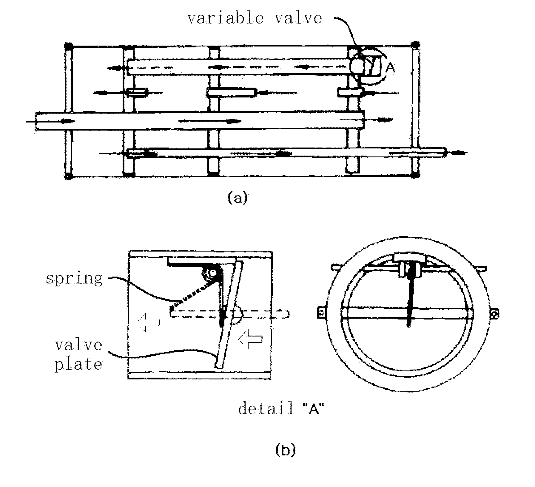
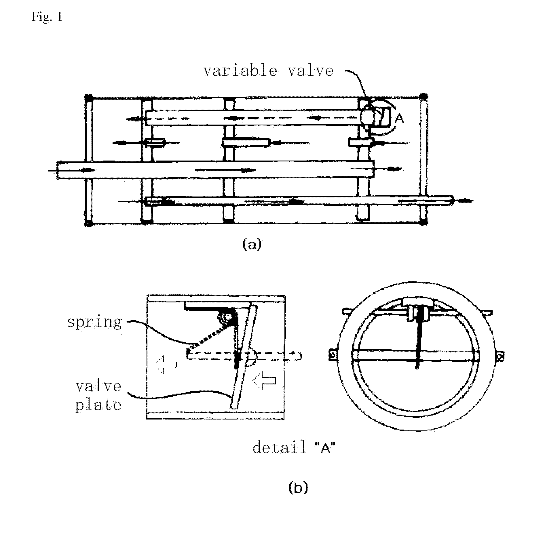
[0012]An aperture-shaped variable valve according to the present invention has a plurality of aperture plates arranged in a ring shape by overlapping each other on an aperture frame to form a semi-spherical or cone aperture surface. A hinge is formed in a front side o...


PUM


Abstract

The present invention relates to an aperture-shaped variable valve which is attached to the inside or end of a pipe to variably control the flow rate or pressure of fluid, such as liquid or gas, flowing along the pipe. As to one usage of the invention, the exhaust noise of an automobile can be controlled because back pressure is variably controlled by the valve attached to a vehicular exhaust system where the flow rate of exhaust gas varies according to the RPM of an engine. Additionally, the flow rate can be measured within a large range through application of the valve to a flowmeter. An operational principle of the valve is to control the cross section of the flow path by contract or release of aperture plates which are initially opened at a constant size by elasticity of a spring. Using the aperture-shaped variable valve, linear control of flow rate or pressure is facilitated, compared with a conventional disc variable valve. Furthermore, control of flow rate or pressure is enabled by a simple method so constitution of a control system is facilitated.

Description

TECHNICAL FIELD[0001]The present invention relates to a valve which controls a flow rate of fluid, and more particularly, to an aperture-shaped variable valve which is attached to the inside or end of a pipe to variably control the flow rate or pressure of fluid, such as liquid or gas, changing the flow rate at any time and flowing along the pipe.BACKGROUND ART[0002]Typical control valves including disc variable valves used for the purposes of controlling the flow rate hardly control the flow rate precisely since the location of the opening / closing part of the valves and the open area of the flow path are not linearly related. Also, the shape of the flow path inside the valve drastically changes to fluctuate the velocity and pressure of fluid to thereby cause a turbulent flow, resulting in great pressure loss, flow noise and vibration. If the fluid is liquid, a very low pressure is partially formed inside the fluid and the separated gas of the liquid generates cavitations. To contro...

Claims


Application Information

Patent Timeline
Patent Type & Authority Applications(United States)
IPC IPC(8): F01L13/00
CPCF16K3/314F16K3/03F01N1/166Y10T137/7898F16K13/00F16K1/36
Inventor LEE, KEUN SANG
Owner LEE KEUN SANG
Why Eureka
Try Eureka