Method for creating drive pattern for galvano-scanner system

a technology of galvanoscanner and drive pattern, which is applied in the field of creating a drive pattern for a galvanoscanner system, can solve the problems of time-consuming and complicated creation of drive pattern input commands, and achieve the effect of short space of time and simple procedur

Active Publication Date: 2011-12-15
HARMONIC DRIVE SYST IND CO LTD
View PDF6 Cites 7 Cited by
  • Summary
  • Abstract
  • Description
  • Claims
  • Application Information

AI Technical Summary

Benefits of technology

[0030]According to the method for creating a drive pattern for a galvano-scanner system of the present invention, a visible laser beam is scanned along each of the positioning points displayed on the surface of the master work, positional information of the galvano-scanner in a state of being aligned at each of the positioning points is obtained, and a drive pattern for scanning the main laser beam is created based on the positional information. Therefore, it is possible to create, through a simple procedure and in a short space of time, a drive pattern from which errors arising from distortion of the optics system of the galvano-scanner, the response characteristics of the galvano-scanner, the distance to the work surface, and other causes of error are removed, without performing an operation of entering correction data or similar data for removing the effect of such errors.

Problems solved by technology

Therefore, creation of a drive pattern input command is time-consuming and requires a certain amount of preparation time and relevant expertise.

Method used


Image

  • Method for creating drive pattern for galvano-scanner system
  • Method for creating drive pattern for galvano-scanner system
  • Method for creating drive pattern for galvano-scanner system

Examples


first embodiment

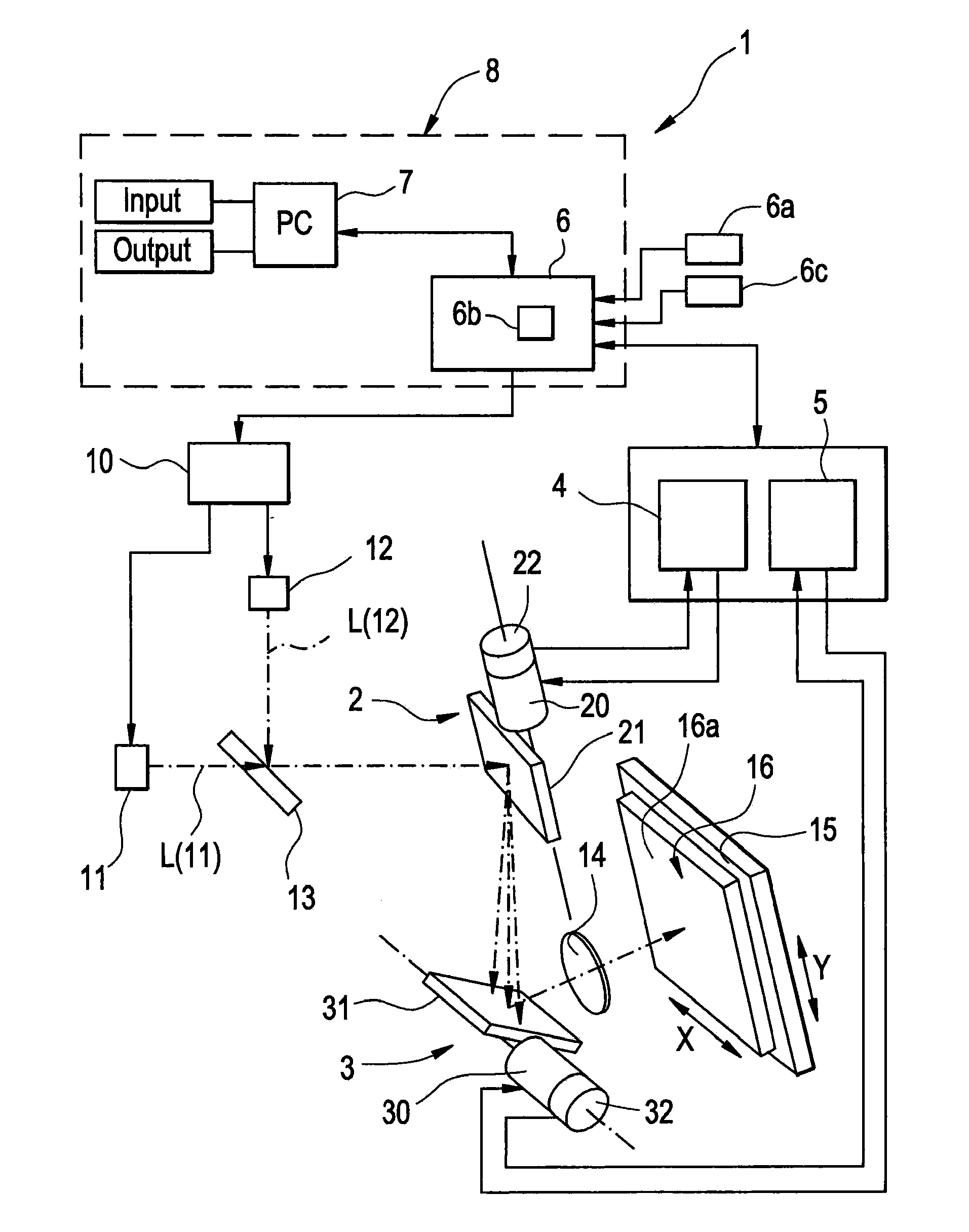
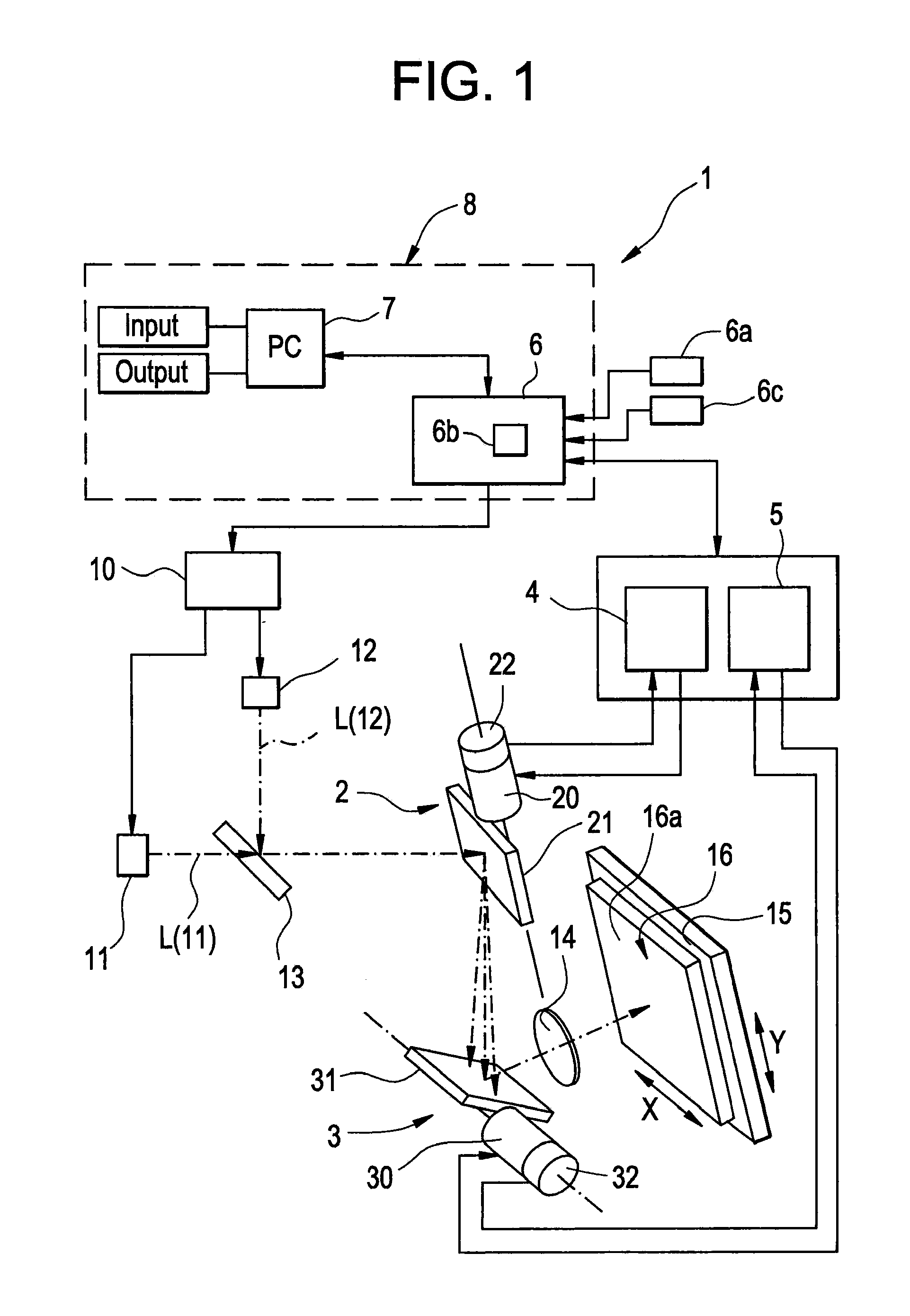
[0044]FIG. 1 is a schematic diagram of a galvano-scanner system according to a first embodiment. A galvano-scanner system 1 comprises an x-axis galvano-scanner 2; a y-axis galvano-scanner 3; an x-axis scanner driver 4 and a y-axis scanner driver 5 for driving the galvano-scanners; and a command generator 8, the command generator 8 having an analog controller 6 and a personal computer 7 or a similar device, for controlling the x-axis and y-axis scanner drivers 4, 5.

[0045]The galvano-scanner system 1, used as, for example, a laser marking device, comprises a marking laser beam source 11 and a visible laser beam source 12. The marking laser beam source 11 is driven via a driver 10 to generate a marking laser beam L (11), which is irradiated onto an x-axis scanning mirror 21 of the x-axis galvano-scanner 2 via a half mirror 13 used as a beam path combining element. The marking laser beam L (11) is reflected by the x-axis scanning mirror 21, then irradiated onto a y-axis scanning mirror ...

second embodiment

[0060]In the method for creating a drive pattern described above, it is necessary to make available a master work for each iteration of work, scan the visible laser beam along each of the positioning points, and create a drive pattern. An instance in which marking or another laser processing is performed on a variety of types of work requires that the teaching operation by the visible laser beam for creating the drive pattern is performed for each iteration of work, and is therefore cumbersome.

[0061]It is therefore preferable that the teaching operation for the positioning points using a master work is performed once only, thereby creating an error correction map or an error correction function, and correcting a design coordinates data based on the error correction map or the error correction function.

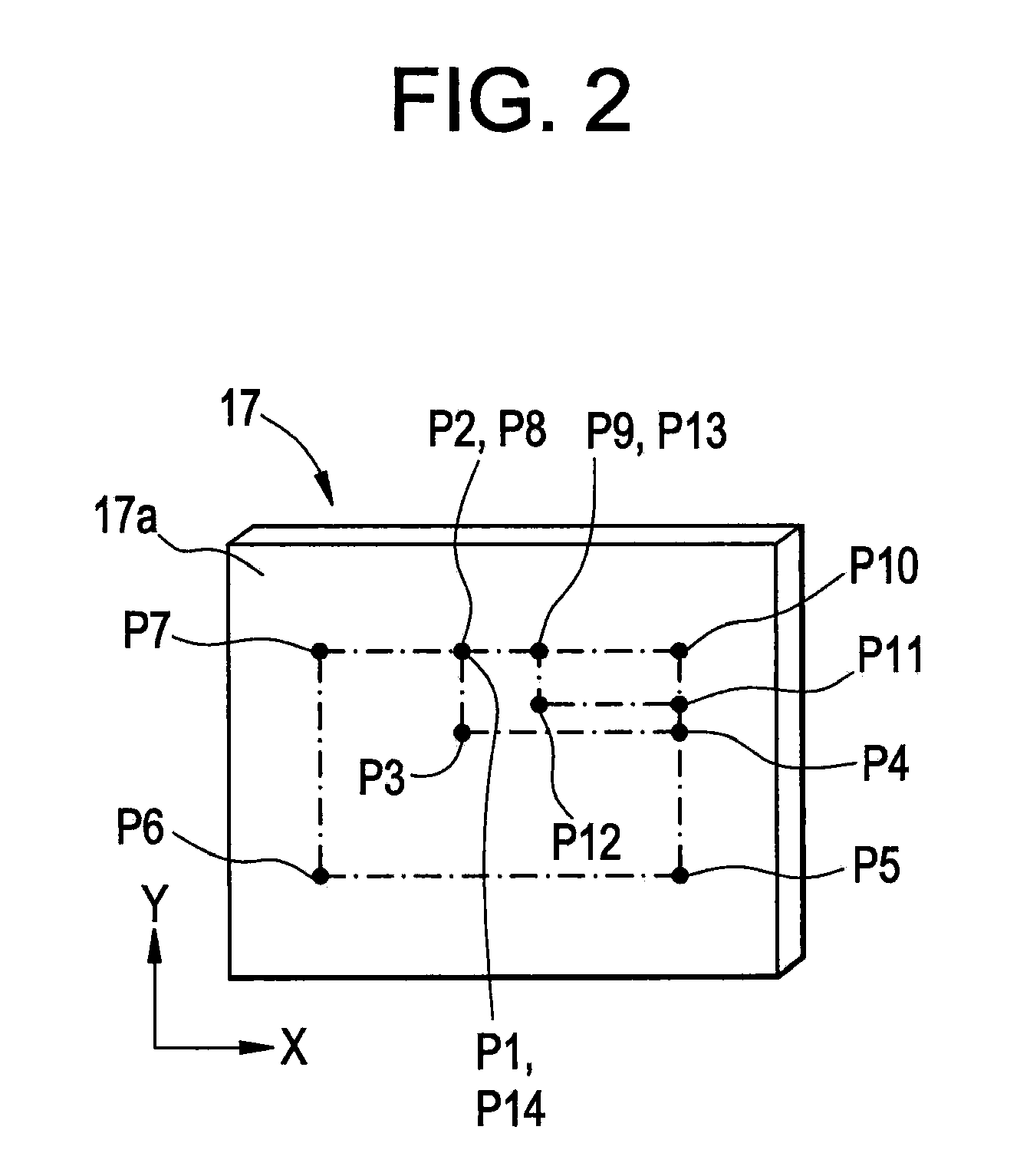
[0062]In such an instance, a master work is made available, the master work having positioning points, each of which being provided at a representative position on a surface. A beam sp...

third embodiment

[0067]Normally, the galvano-scanner system 1 is driven according to a drive pattern that is in accordance with adjustment conditions that have been set in advance, and a maximum degree of responsiveness and positional accuracy can thereby be obtained. Often, in an instance in which the galvano-scanner system is driven according to a drive pattern under conditions that are more severe than the adjustment conditions, overshooting occurs during alignment at a positioning point, vibration about the positioning point occurs, and responsiveness and accuracy of alignment decrease. FIG. 7(a) shows an example of a driving operation (i.e., actual movement) performed in accordance with a drive pattern (i.e., command input value) having a small vibration width in accordance with adjustment conditions set in advance, and FIG. 7(b) shows an example of a driving operation due to a drive pattern having a large vibration width exceeding the adjustment conditions.

[0068]In order to decrease the tact t...


PUM

PropertyMeasurementUnit
speedaaaaaaaaaa
timeaaaaaaaaaa
distanceaaaaaaaaaa

Abstract

A visible laser beam scanned by a galvano-scanner system is aligned at each of positioning points on the top surface of a master work by manual operation to record sensor position signals of position sensors on galvano-scanners. The sensor position signals on each positioning point are recorded to create a drive pattern in accordance with recorded sensor position signals. The drive pattern no longer has optics system error sources including focus error and attachment error as well as errors caused by scale, offset and the like, also eliminating the need for entering a distance as far as the top surface of the work. Therefore, the drive pattern with error components removed can be created with ease.

Description

TECHNICAL FIELD[0001]The present invention relates to a method for creating a drive pattern for a galvano-scanner system, wherein a visible laser beam is scanned via each positioning point on a surface of a work, and a drive pattern for scanning a main laser beam is thereby created.BACKGROUND ART[0002]A galvano-scanner system is used to scan a laser beam according to a predetermined drive pattern in a laser processing device or a similar device. For example, in a laser marking device, there is provided a galvano-scanner system comprising an x-axis galvano-scanner and a y-axis galvano-scanner, a laser beam emitted from a laser beam source is two-dimensionally scanned by the scanners along a surface of a work according to a predetermined drive pattern, and a predetermined marking is applied to the work surface.[0003]A drive pattern input command for a conventional galvano-scanner system is created by entering, in a manner similar to that for a timing chart, coordinates data representi...

Claims


Application Information

Patent Timeline
Patent Type & Authority Applications(United States)
IPC IPC(8): G03B27/54
CPCB23K26/0807B23K26/0853H04N3/10H04N3/08G02B27/0031B23K26/082
Inventor TANIOKA, NOZOMU
Owner HARMONIC DRIVE SYST IND CO LTD
Why Eureka
Try Eureka