Audio output drivers for piezo speakers

a piezoelectric speaker and audio output technology, applied in piezoelectric/electrostrictive transducers, transducer types, frequency response correction, etc., can solve the problem of inefficiency of converting electrical energy to sound using electro-magnetic speakers, power consumption of audio devices is the output stage, etc. problem, to achieve the effect of improving low frequency response, high efficiency, and increasing high frequency harmonics

Active Publication Date: 2011-12-15
WISILICA INC
View PDF4 Cites 18 Cited by
  • Summary
  • Abstract
  • Description
  • Claims
  • Application Information

AI Technical Summary

Benefits of technology

[0015]The conversion of electrical power to an audio signal for a typical piezoelectric speaker is a nonlinear function. In particular, lower frequencies are not well converted to sound from the speaker, for instance the frequency response of piezoelectric speakers drops off significantly below 1 KHz. The low frequency response can be improved by increasing the high frequency harmonics of the signal driving the piezoelectric speaker. A first embodiment of the present invention applies a high frequency noise shaping function, for example delta sigma modulation, to cause high frequency signal components to excite the piezoelectric speaker without causing significant loss in audio quality, which results in increasing the high frequency harmonics. In a second embodiment of the present invention non-linear functions, for example square-law devices, hard limiting or clipping, are applied to an audio signal to introduce high frequency harmonics to which a piezoelectric speaker is more responsive
[0016]A use of a charge pump to drive a piezoe

Problems solved by technology

A large part of the power consumption of an audio device is the output stages or power of the power amplifier section.
Most audio devices use traditional electro-magnetic speakers, which present an electrical resistance and consume power as a result of the resistance, wherein only a small portion of the output energy is converted to an audio signal.
The inefficiency of converting electrical energy to sound using electro-magnetic speakers is a reality with all audio devices regar

Method used


Image

  • Audio output drivers for piezo speakers
  • Audio output drivers for piezo speakers
  • Audio output drivers for piezo speakers

Examples


Embodiment Construction

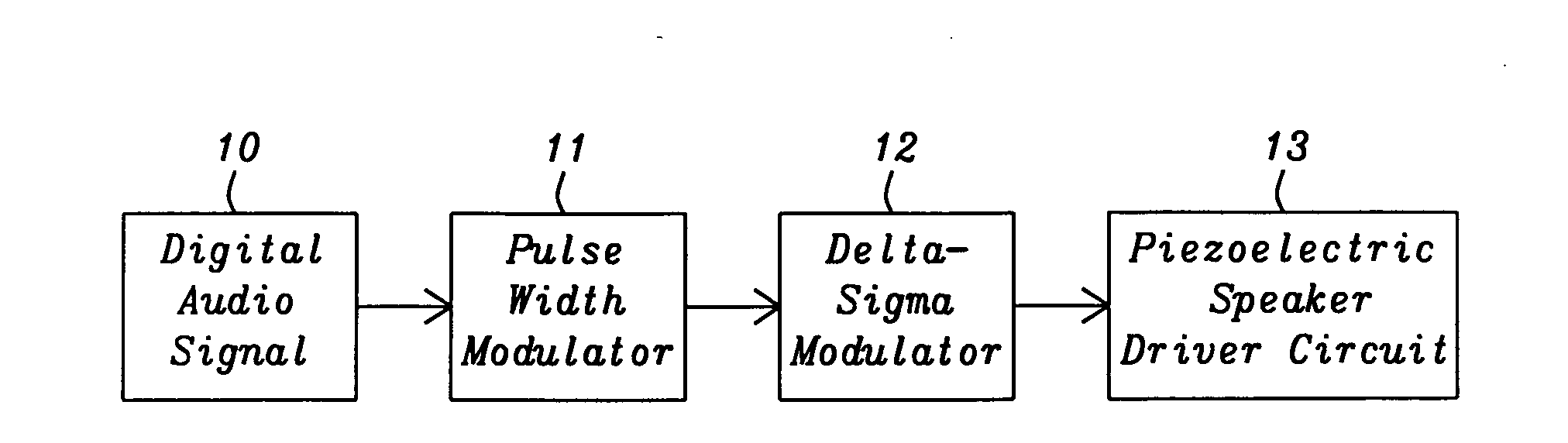
[0025]In FIG. 1 is a block diagram of the present invention where a digital audio signal 10 is fed first through a pulse width modulator 11 and then fed through a delta sigma modulator 12 to provide a signal to drive a piezoelectric speaker driver circuit. 13. Low frequency response of the piezoelectric speaker is enhanced by an increase in high frequency harmonic content of the signal applied to the piezoelectric speaker. A high frequency noise shaping function of the delta sigma modulation, for instance, introduces high frequency signal components to excite the piezoelectric speaker without causing a significant loss in audio quality. Also nonlinear functions such as square law, hard limiting or clipping devices that are applied to the audio signal introduce high frequency harmonics to which the piezoelectric speaker responds favorably, and for the same audio output the input can be reduced to save power consumption.

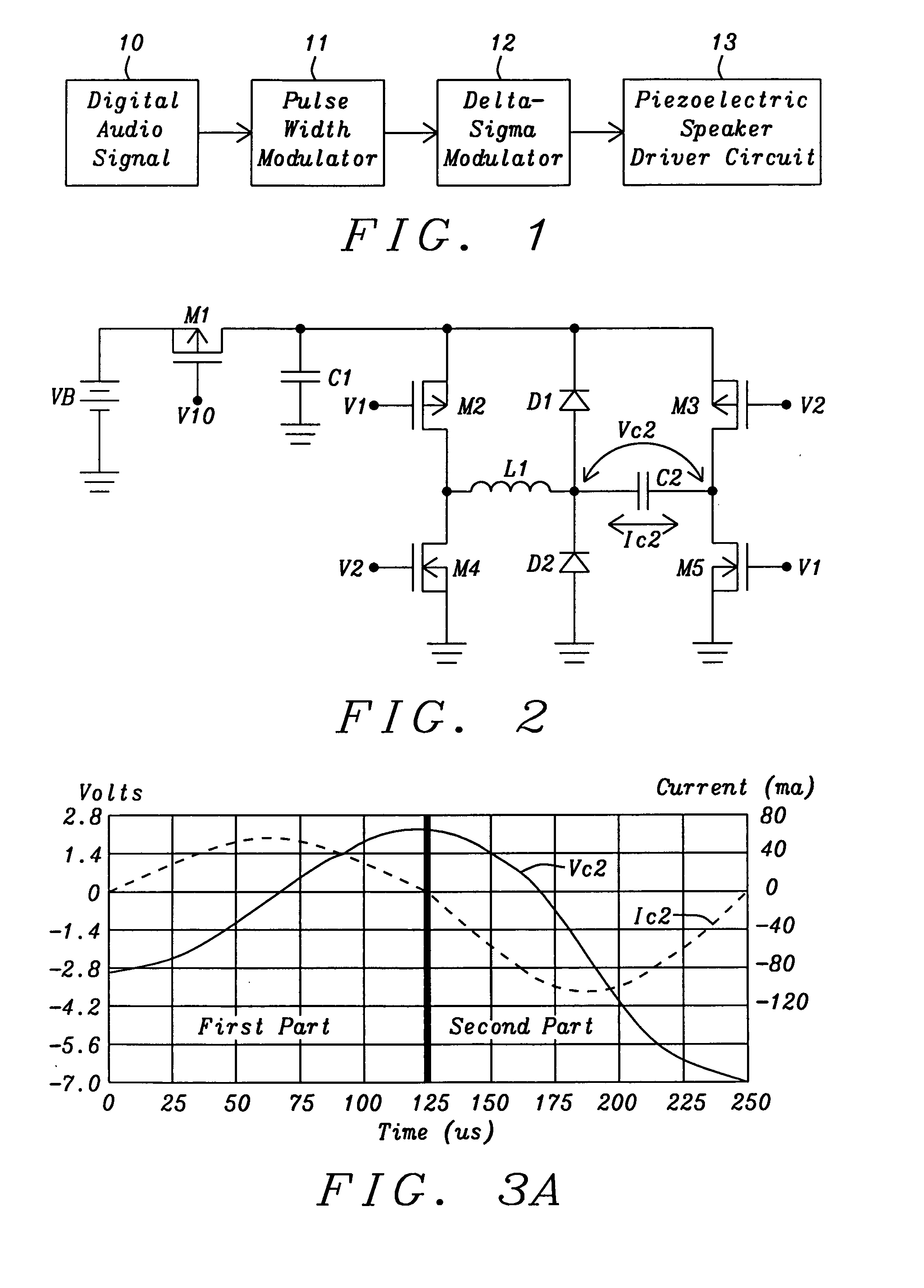
[0026]FIG. 2 is a circuit diagram of the first embodiment of pres...


PUM


Abstract

A driver circuit for a piezoelectric speaker is described, wherein charge is transferred from a charge reservoir to the speaker. In a first embodiment a delta sigma circuit uses a pulse width modulated digital audio signal to control a push-pull circuit to drive the piezoelectric speaker. High frequency harmonics are introduced to the delta sigma drive signals to enhance the low frequency response of the speaker. A charge recovery mechanism recovers charge from the speaker to reduce the frequency of replenishing the charge reservoir and to provide additional drive current for the speaker. In a second embodiment the pulse width modulated signal is used to drive a voltage quadrupling circuit that drives the piezoelectric speaker, wherein the reservoir capacitor is integrated with the capacitors of quadrupling circuit, which provides charge recovery.

Description

[0001]This application claims priority to Provisional Patent Application Ser. No. 61 / 397,664, filed on Jun. 15, 2010, which is herein incorporated by reference in its entirety.BACKGROUND OF THE INVENTION[0002]1. Field of Invention[0003]This invention is related to driver circuits and in particular audio output drivers for piezoelectric speakers.[0004]2. Description of Related Art[0005]A large part of the power consumption of an audio device is the output stages or power of the power amplifier section. It is particularly critical for portable devices powered by batteries to conserve power to reduce battery drain. Most audio devices use traditional electro-magnetic speakers, which present an electrical resistance and consume power as a result of the resistance, wherein only a small portion of the output energy is converted to an audio signal. The inefficiency of converting electrical energy to sound using electro-magnetic speakers is a reality with all audio devices regardless of the ...

Claims


Application Information

Patent Timeline
IPC IPC(8): H04R17/00
CPCH04R17/00H04R3/04
Inventor KWAN, DENNISSINGAMSETTY, SURESHHSIEH, JEFFREY
Owner WISILICA INC
Why Eureka
Try Eureka