Method of selectively etching an insulation stack for a metal interconnect

a technology of metal interconnections and stacks, applied in the direction of electrical equipment, basic electric elements, electric discharge tubes, etc., can solve the problems of many challenges in the implementation of low-k materials in the stacks of insulation layers for metal interconnections, and the delay of interconnections is a major limitation

Active Publication Date: 2011-12-15
TOKYO ELECTRON LTD
View PDF8 Cites 58 Cited by
  • Summary
  • Abstract
  • Description
  • Claims
  • Application Information

AI Technical Summary

Benefits of technology

[0002]The invention relates to a method for selectively etching a pattern in an insulation stack and, in particular, a method fo

Problems solved by technology

As is known to those in semiconductor device manufacturing, interconnect delay is a major limiting factor in the drive to improve the speed and performance o

Method used


Image

  • Method of selectively etching an insulation stack for a metal interconnect
  • Method of selectively etching an insulation stack for a metal interconnect
  • Method of selectively etching an insulation stack for a metal interconnect

Examples


Embodiment Construction

[0025]In the following description, for purposes of explanation and not limitation, specific details are set forth, such as a particular geometry of a processing system, descriptions of various components and processes used therein. However, it should be understood that the invention may be practiced in other embodiments that depart from these specific details.

[0026]Similarly, for purposes of explanation, specific numbers, materials, and configurations are set forth in order to provide a thorough understanding of the invention. Nevertheless, the invention may be practiced without specific details. Furthermore, it is understood that the various embodiments shown in the figures are illustrative representations and are not necessarily drawn to scale.

[0027]Various operations will be described as multiple discrete operations in turn, in a manner that is most helpful in understanding the invention. However, the order of description should not be construed as to imply that these operations...


PUM


Abstract

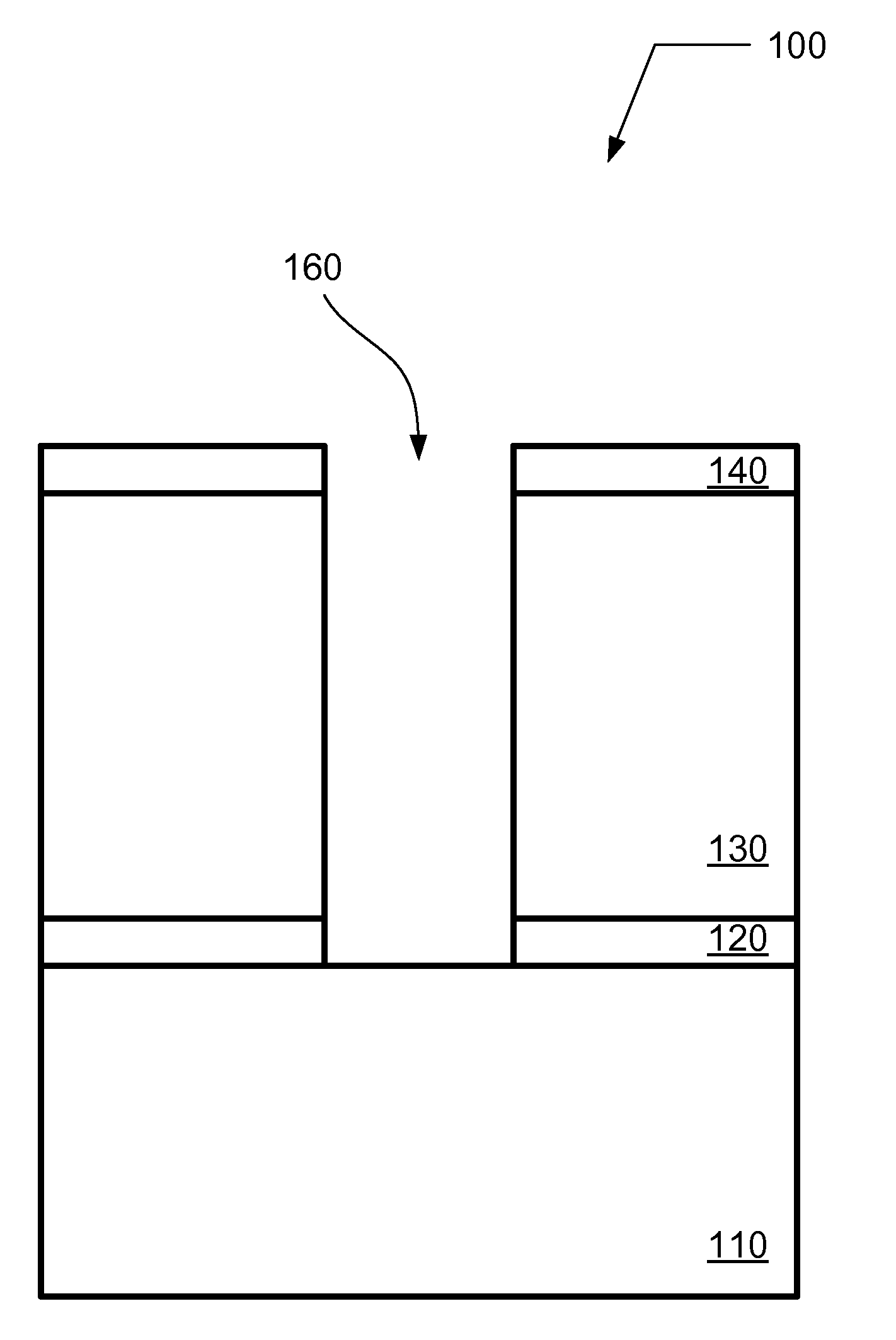
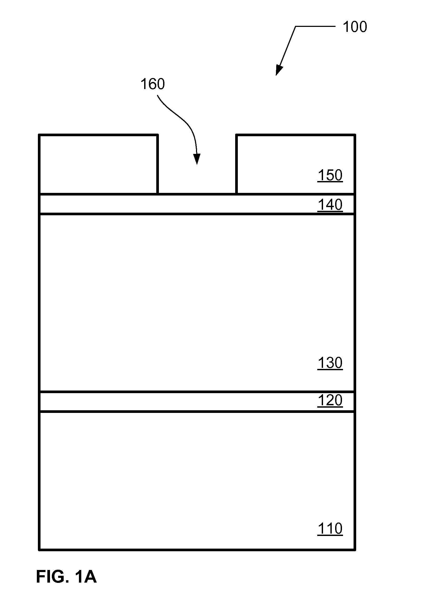
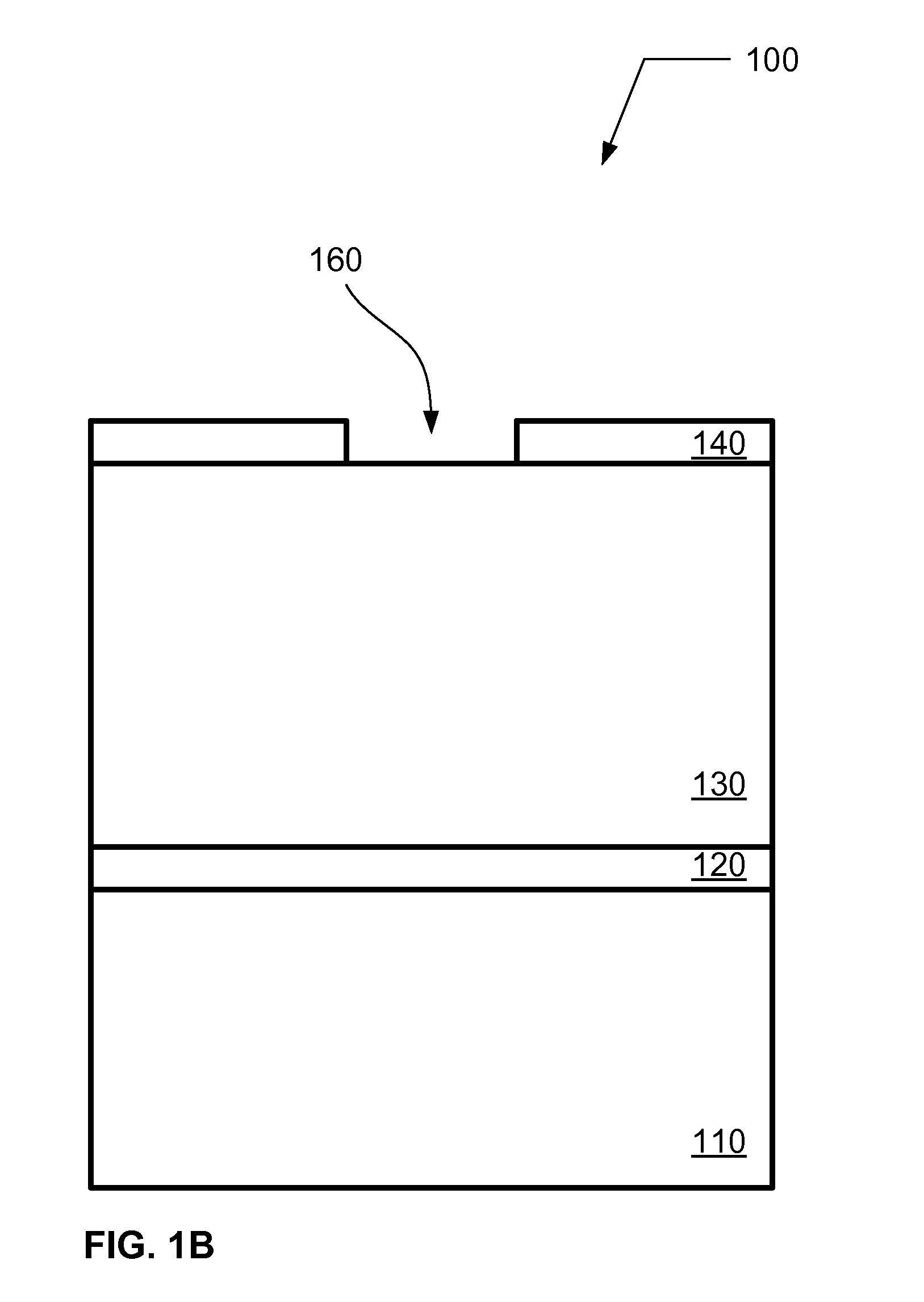
A method of patterning an insulation layer is described. The method includes preparing a film stack on a substrate, wherein the film stack comprises a cap layer, a SiCOH-containing layer overlying the cap layer, and a hard mask overlying the SiCOH-containing layer. The method further includes transferring a pattern through the film stack by performing a series of etch processes in a plasma etching system, wherein the series of etch processes utilize a temperature controlled substrate holder in the plasma etching system according to a substrate temperature control scheme that achieves etch selectivity between the SiCOH-containing layer and the underlying cap layer.

Description

BACKGROUND OF THE INVENTION[0001]1. Field of Invention[0002]The invention relates to a method for selectively etching a pattern in an insulation stack and, in particular, a method for selectively etching a trench-via structure in a low dielectric constant (low-k) insulation stack for subsequent metallization.[0003]2. Description of Related Art[0004]As is known to those in semiconductor device manufacturing, interconnect delay is a major limiting factor in the drive to improve the speed and performance of integrated circuits (IC). One way to minimize interconnect delay is to reduce interconnect capacitance by using low dielectric constant (low-k) materials and ultra-low-k dielectric materials in metal interconnects during back-end-of-line (BEOL) operations for IC production. Such low-k materials presently include organosilicon glass or SiCOH-containing materials.[0005]Thus, in recent years, low-k materials have been developed to replace relatively high dielectric constant insulating ...

Claims


Application Information

Patent Timeline
IPC IPC(8): H01L21/3065
CPCH01J37/32082H01L21/31116H01L21/6831H01L21/76832H01L21/76807H01L21/76811H01L21/76829H01L21/76802H01L21/67248
Inventor ZIN, KELVIN
Owner TOKYO ELECTRON LTD
Why Eureka
Try Eureka