Electromagnetic load device for an apparatus for physical exercise, and apparatus provided with said device

a technology of electromagnetism and load device, which is applied in the direction of sports equipment, dynamo-electric machines, single motor speed/torque control, etc., can solve the problems of unsolved problems, vary load, and inability to follow the execution of advanced training programs, so as to improve the quality of physical training, and improve the effect of safety

Inactive Publication Date: 2011-12-15
MASSA ENRICO
View PDF9 Cites 20 Cited by
  • Summary
  • Abstract
  • Description
  • Claims
  • Application Information

AI Technical Summary

Benefits of technology

[0021]The aim of the present invention is to provide an electromagnetic load device for a physical apparatus, and a physical apparatus equipped with said device, that resolves completely all the previously explained inconvenients, therefore able to improve noticeably the quality of the training and able to resolve problems like the weight and encumbrance of the current machines, obtaining also an higher safety. The apparatus

Problems solved by technology

This load technique for machines for physical exercise presents a series of inconvenients unsolved to date.
First of all the significant weight of the whole machine (when loaded with the ballasts), that constitutes an inconvenient in the home use, where it is often necessary to move the machine.
Besides there is a problem of comfort and security, given by the manipulation of the modular ballasts and their load/unload on the machine.
Again, it is impossible to vary the load during the exercise, that means it is impractical to follow the execution of advanced training programs, like those in which the load changes during the exercise or adaptive, like for example a program in which the athlete generates with his muscular strain a fixed power.
The weights—by their same nature—are bounded to work substantially with vertical movements and so they involve constrains in the design of the machines, besides producing considerable burden.
These methods even if they present the advantage of being able to control electronically the load do not resolve the problem of the high weight and encumbrance of the machine.
This method, together with others, that utilize standard electric motor, requires however to be coupled with complex apparatus like gears, reducers and transmission clutches in order to transform the rotational movement in linear movement and this causes problems of reliability, encumbrance, cost and difficulty in manufacturing.
Such systems however have the defect of being heavy, cumbersome and complex, also they require a constant maintenance, and are subject to problems like the loss of the working fluid.
Finally elect

Method used


Image

  • Electromagnetic load device for an apparatus for physical exercise, and apparatus provided with said device
  • Electromagnetic load device for an apparatus for physical exercise, and apparatus provided with said device
  • Electromagnetic load device for an apparatus for physical exercise, and apparatus provided with said device

Examples


Embodiment Construction

OF PREFERRED EMBODIMENT

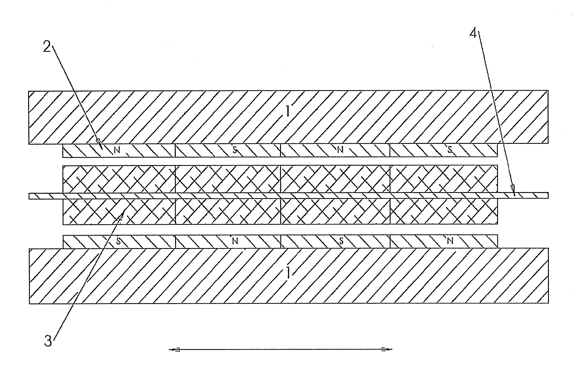
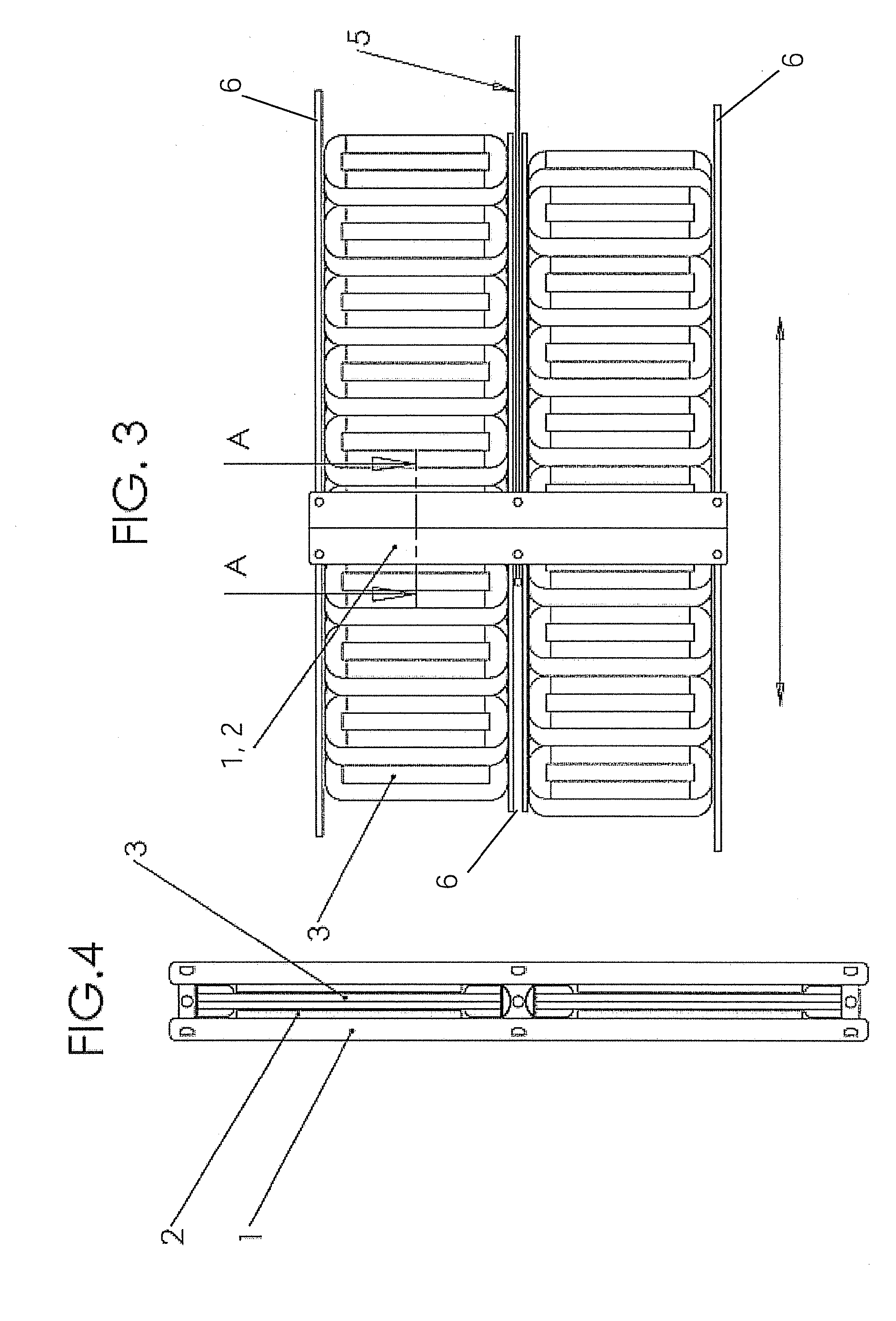
[0043]With reference to FIG. 1, are shown the components of a linear electric motor. With reference to the figures, in particular FIG. 3, 4, 5 e FIG. 10, 11, 12, is shown the preferred embodiment of the linear electric motor that generates the force, being part of the load device under the present invention. In the first embodiment the two groups of coils are placed side by side, in the second are superimposed on two parallel planes.

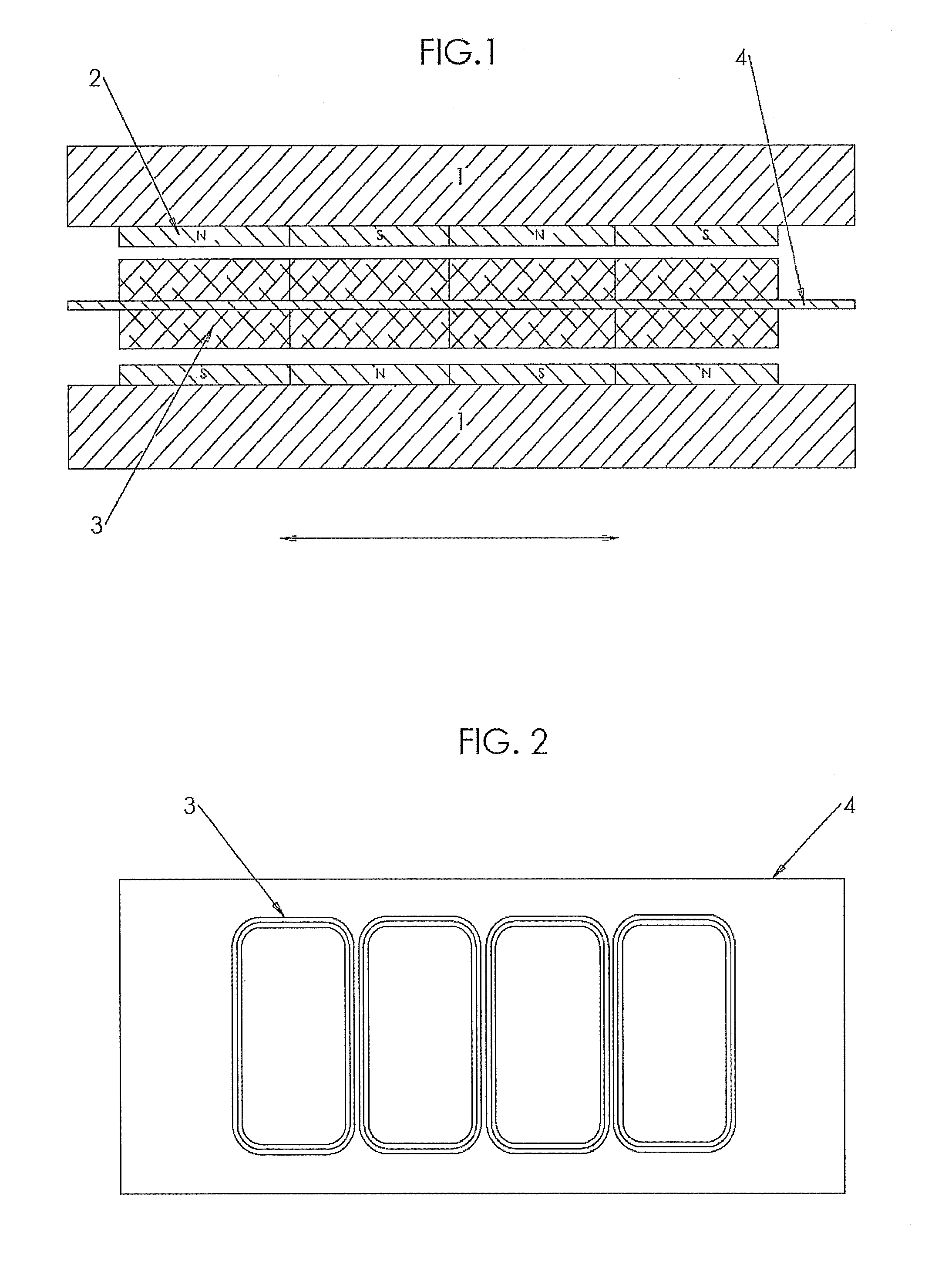
[0044]In the figures are highlighted the ferromagnetic cores 1, the permanent magnets 2, the coils 3 of conductive material powered by an electric current and a structural support 4 for the coils 3 of a material of high thermal conductivity. Moreover is presented a means to be connected mechanically 5 to the desired exercise machine of a known type.

[0045]In particular in FIG. 6, 7, 8, 13, 14 is shown in detail a preferred embodiment of the coils 3.

[0046]The system that produces the load sustained by the athlete, also called linear ...


PUM


Abstract

A load device for an apparatus for physical exercise that comprises a device that generate the load called linear motor, a micro controller, a series of sensors (dynamic, diagnostic and physiological) and a user interface.

Description

FIELD OF THE INVENTION[0001]The present invention refers to an electromagnetic load device for an apparatus for physical exercise, and to an apparatus provided with said device.STATE OF THE ART[0002]In the last years there has been a renewed interest towards a regular and systematic physical exercise with the aim to promote the health of a person, to increase physical qualities like strength and resistance and to reach a determined physical shape.[0003]Many people, professionals and not, spend lots of time using these apparatus, in particular professional athletes that compete to reach the best possible results. As it is known, in the field of fitness machines, several configurations of apparatus exist, each one able to train the desired muscles of the athlete following suitable schemes.[0004]Many of these machines utilize ballasts or weights to reach a sufficient load for the programmed muscles training.[0005]Said weights are typically formed by disks or parallelepipeds of high spe...

Claims


Application Information

Patent Timeline
IPC IPC(8): A63B21/005H02P6/08H02P9/04H02K41/02
CPCA63B21/005A63B21/0052A63B21/0053A63B21/0058A63B2220/13H02K49/06A63B2230/00A63B2230/06H02K3/47H02K7/1869H02K41/031A63B2220/30
Inventor MASSA, ENRICO
Owner MASSA ENRICO
Why Eureka
Try Eureka