Device for determining the concrete cover of reinforcements during casting

Inactive Publication Date: 2011-12-22
KUSSNER EBERHARD +2
View PDF14 Cites 3 Cited by
  • Summary
  • Abstract
  • Description
  • Claims
  • Application Information

AI Technical Summary

Benefits of technology

[0009]The fastening may present a section capable of at least partially encompassing a steel bar of a reinforcement, for example in the form of an essentially U-shaped recess. This U-shaped recess may for example present a width in the range of 5 to 25 mm, preferably in the range of 10 to 20 mm and for example a depth in the range of 5 to 30 mm, preferably in the range of 15 to 25 mm. By means of an appropriately dimensioned recess, a rebar of usual commercially available dimension may be passed through and therefore a device is easily fixable to such a bar by means of an appropriately dimensioned U-shaped recess.
[0010]In order to improve fixing of th

Problems solved by technology

After concreting, the reinforcement must not have any direct contact with the atmosphere surrounding the concrete components, since this would result in the long term in corrosion damage to the reinforcement or damage to the latter in the case of effects of fire.
In practice, it is desired that the concrete cover should not be too large, since in this case, the concrete components may become too heavy, which may cause problems for example during transport or static problems when installing these concrete components in a structu

Method used


Image

  • Device for determining the concrete cover of reinforcements during casting
  • Device for determining the concrete cover of reinforcements during casting
  • Device for determining the concrete cover of reinforcements during casting

Examples


Embodiment Construction

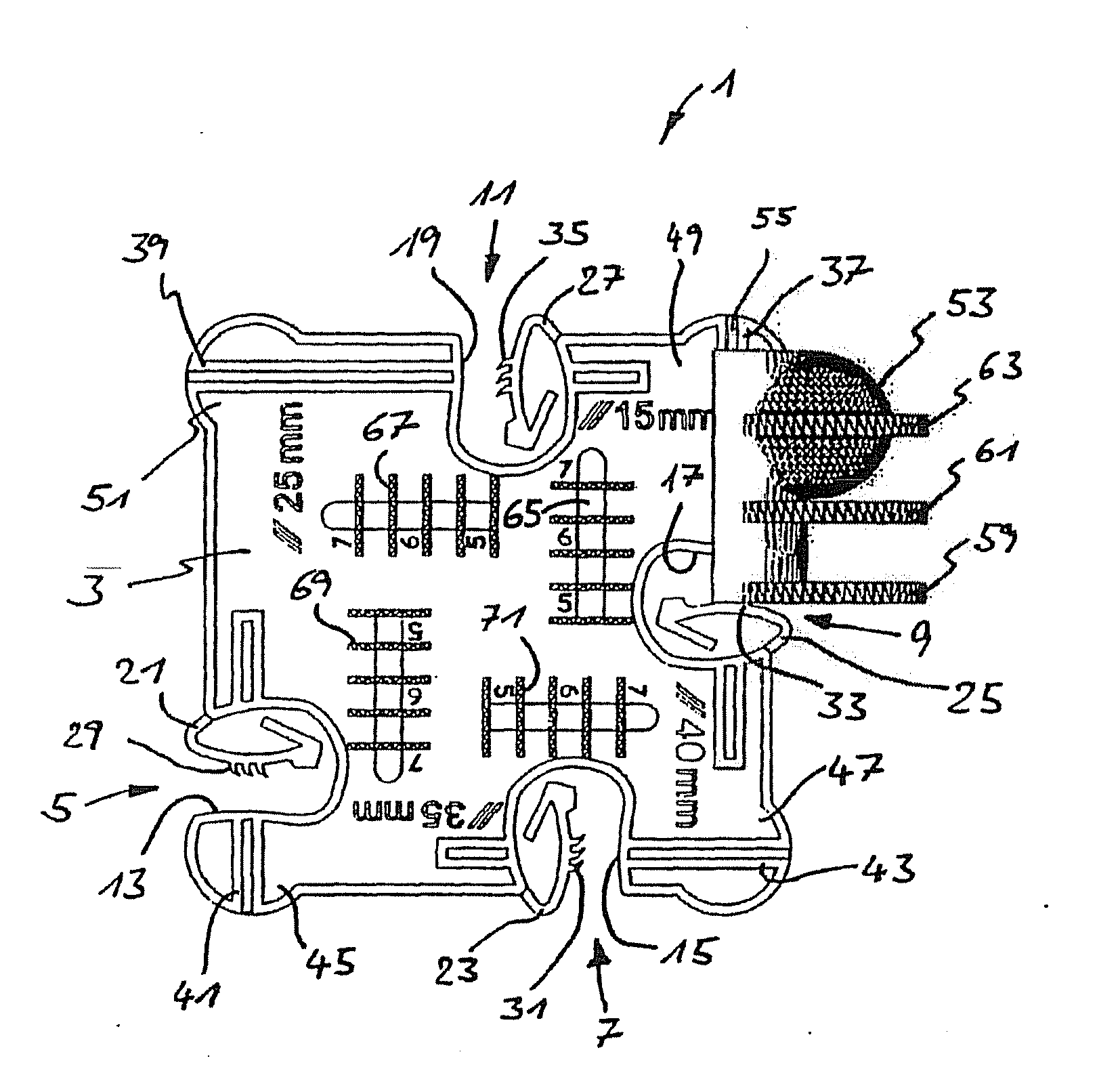
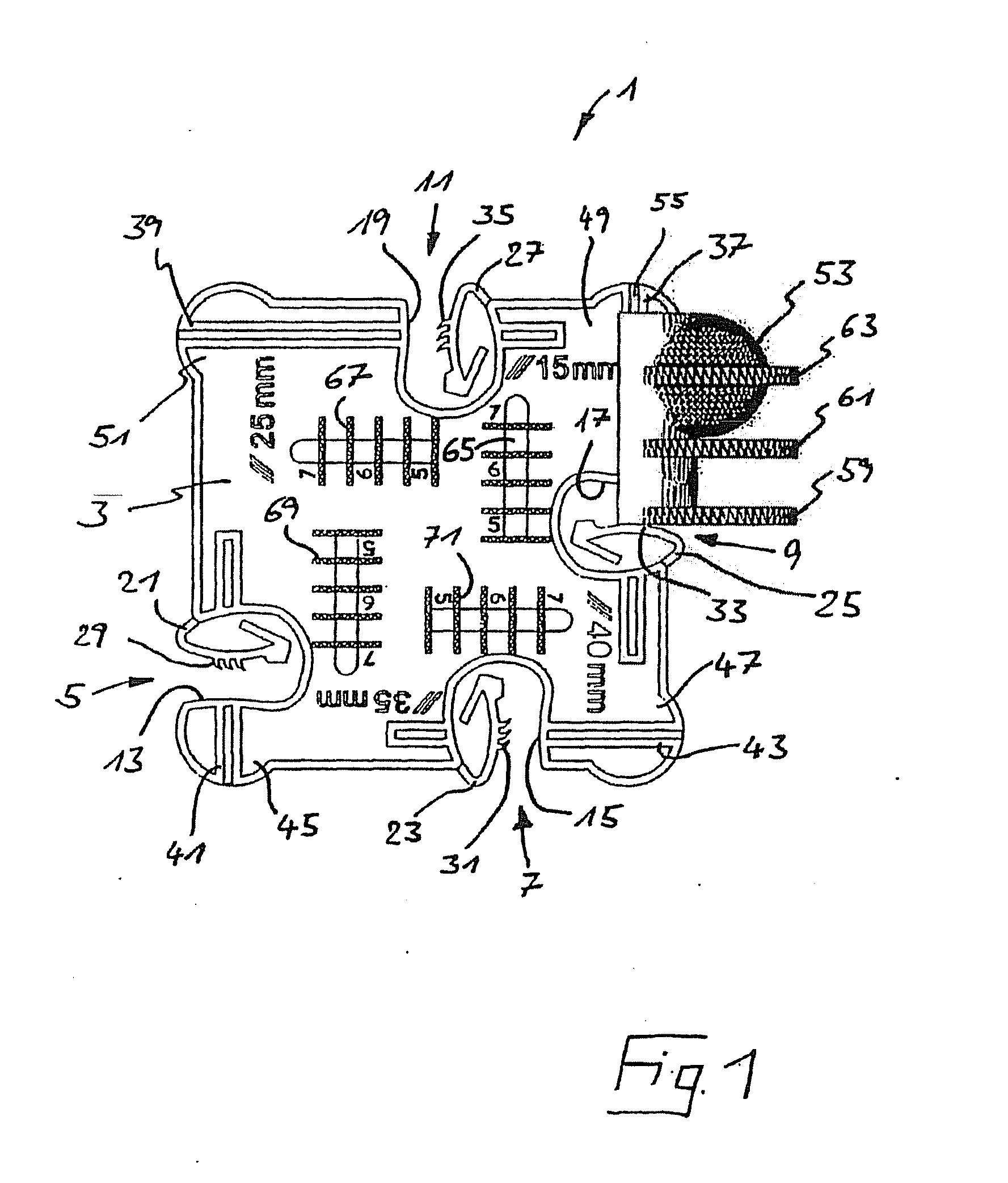
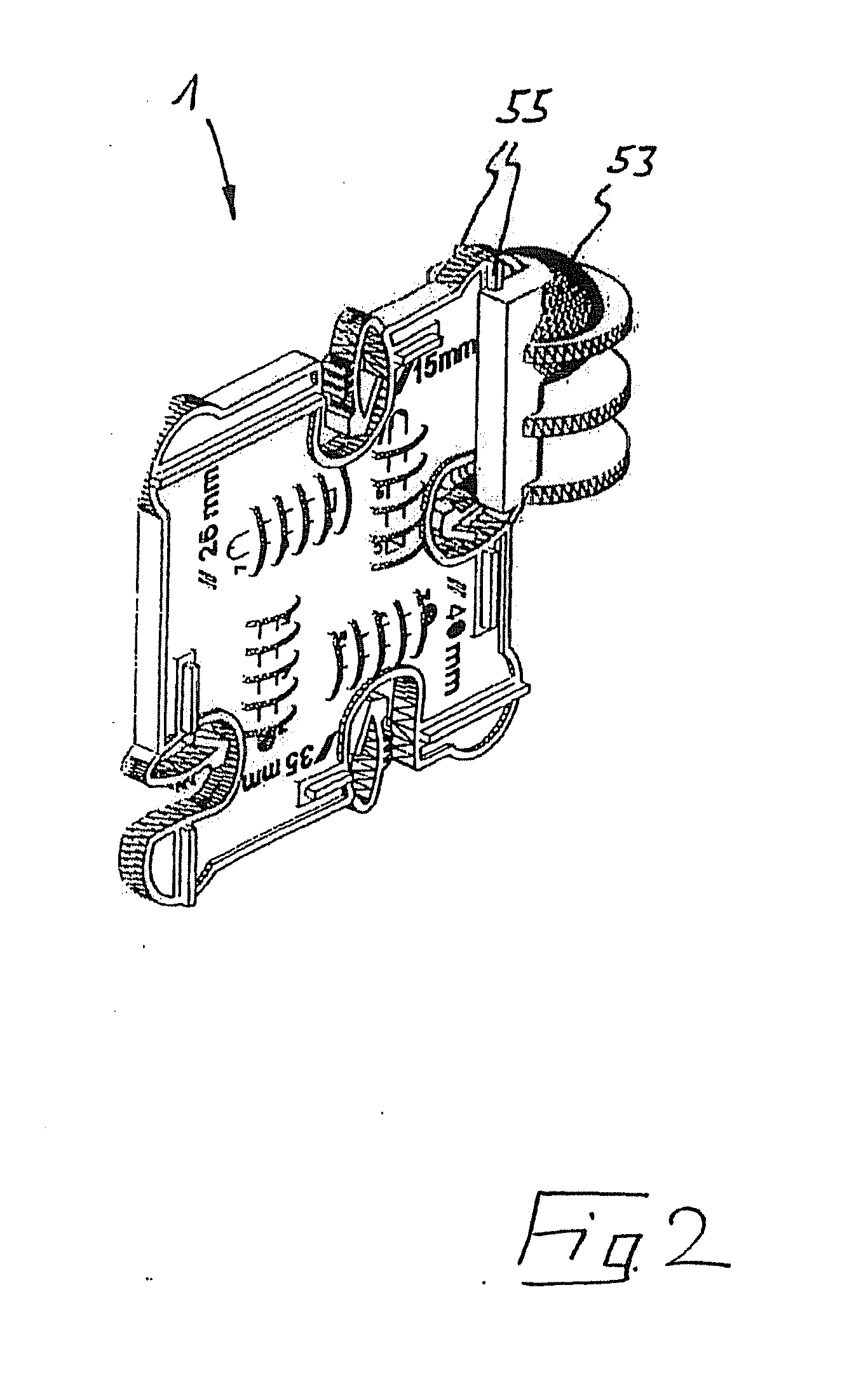
[0033]The device according to FIG. 1 is designated in its entirety by the reference 1. It presents an essentially cuboid base body 3 with opposite, essentially rectangular base areas. The base body 3 has protrusions at its four corners. In the area of the four side edges of the base body 3, a fastening 5, 7, 9, 11 is arranged on the latter respectively. Each fastening 5, 7, 9, 11 presents an essentially U-shaped recess 13, 15, 17, 19 respectively, each with an internal clamping system in the form of a spring arm 21, 23, 25, 27. Each spring arm 21, 23, 25, 27 presents three serrated protrusions 29, 31, 33, 35 respectively.

[0034]Each fastening 5, 7, 9, 11 is respectively dimensioned in such a way that as a result a steel bar of a reinforcement is fixable by partial encompassment and the device 1 is fixable by clamping on the encompassed steel bar. For this purpose, the U-shaped recesses 13, 15, 17, 19 of the fastenings 5, 7, 9, 11 respectively present a width of approximately 15 mm an...


PUM

PropertyMeasurementUnit
Areaaaaaaaaaaa
Dimensionaaaaaaaaaa
Distanceaaaaaaaaaa

Abstract

The disclosure concerns a device for determining the dimension of the upper concrete cover of a concrete component, having at least one fastening by means of which the device can be fixed to a reinforcement for a concrete component and at least one section capable of projecting above the upper concrete cover during casting in the reinforcement, wherein this section presents means of configuration by which the dimension of the upper concrete cover may be determined.

Description

CROSS-REFERENCE TO RELATED APPLICATIONS[0001]This application is a National Phase Entry of International Application No. PCT / EP2009 / 006944, filed on Sep. 25, 2009, which claims priority to German Patent Application Serial No. 20 2008 013 260.6, filed on Oct. 4, 2008, both of which are incorporated by reference herein.BACKGROUND AND SUMMARY[0002]The invention concerns a device for determining the dimension of the upper concrete cover of a concrete component, a reinforcement for a concrete component in addition to a concrete component.[0003]Concrete components present an internal reinforcement in the form of sectional constructional steels or concrete reinforcing mats. The reinforcement is applied by means of bar spacers at a specific distance in relation to the base on to the production pallet. This reinforcement is cast with concrete in order to manufacture the component. In this case, both the edge distance of the reinforcement in the downwards direction and the edge distance of ce...

Claims


Application Information

Patent Timeline
IPC IPC(8): G01D21/00
CPCE04C5/20E04G21/185E04F21/05
Inventor KUSSNER, EBERHARDRACH, ANDREASZAMPINI, DAVIDE
Owner KUSSNER EBERHARD
Why Eureka
Try Eureka