Egr cooler

a technology of exhaust gas recirculation and cooler, which is applied in the direction of indirect heat exchangers, machines/engines, lighting and heating apparatus, etc., can solve the problems of low bonding strength and cracks in the brazed portion, and achieve the effect of preventing the generation of large stress, facilitating the assembly process and preventing cracks

Inactive Publication Date: 2011-12-22
KOMATSU LTD
View PDF8 Cites 36 Cited by
  • Summary
  • Abstract
  • Description
  • Claims
  • Application Information

AI Technical Summary

Benefits of technology

[0020]According to the aspect of the invention, the shielding member is provided in the inlet tank. Since the exhaust gas having a high temperature introduced into the inlet tank is unlikely to contact with the circumferential wall of the inlet tank, the outward thermal expansion of the circumferential wall is restrained. Thus, the casing and the header plate bonded to the inlet tank are not affected by the thermal expansion of the inlet tank, so that a large deformation in the casing and header plate is unlikely to occur. As a result, generation of a large stress is prevented at the bonding portion between the header plate and each tube and thus no crack occurs.
[0021]According to the arrangement in which the shielding member is provided in the inlet tank, since a core, i.e., the header plate and the tubes, is not provided with the shielding member, the front and rear configurations of the core are identical. Thus, the core is not inadvertently installed back to front in a casing whose front and rear sides are not invertible, which facilitates an assembling process.
[0022]With the clearance formed between the shielding member and the header plate, even when the shielding member is exposed to the exhaust gas and thus thermally expanded, the shielding member is prevented from contacting with the header plate. Thus, the header plate is prevented from being pressed to generate stress.
[0023]According to the arrangement in which the opening of the outlet of the shielding member is sufficiently large to cover the ends of all the tubes, the exhaust gas from the shielding member can be equally fed into the tubes, thereby cooling the exhaust gas with an improved efficiency.
[0024]With the shielding member gradually widened toward the outlet, even when the inlet casing has a small opening area at the inlet thereof while having a large opening area at the outlet thereof, the exhaust gas can be reliably guided into the tubes, thereby providing a favorable cooling efficiency.
[0025]According to the arrangement in which the outlet end for restraining diffusion is provided to the outlet of the shielding member, the exhaust gas can be fed into the tubes without diffusion. Thus, a flow of the exhaust gas becomes smooth, so that cooling efficiency can be further improved.

Problems solved by technology

In the inlet tank, since one surface of the header plate, i.e., the surface opposed to the inlet tank, is directly exposed to the exhaust gas having a high temperature, a brazed portion between the header plate and each tube is heated to a high temperature by the exhaust gas, which lowers the bonding strength therebetween and thus causes a crack in the brazed portion.

Method used


Image

  • Egr cooler
  • Egr cooler
  • Egr cooler

Examples


Embodiment Construction

[0032]An exemplary embodiment of the invention will be described below with reference to the attached drawings.

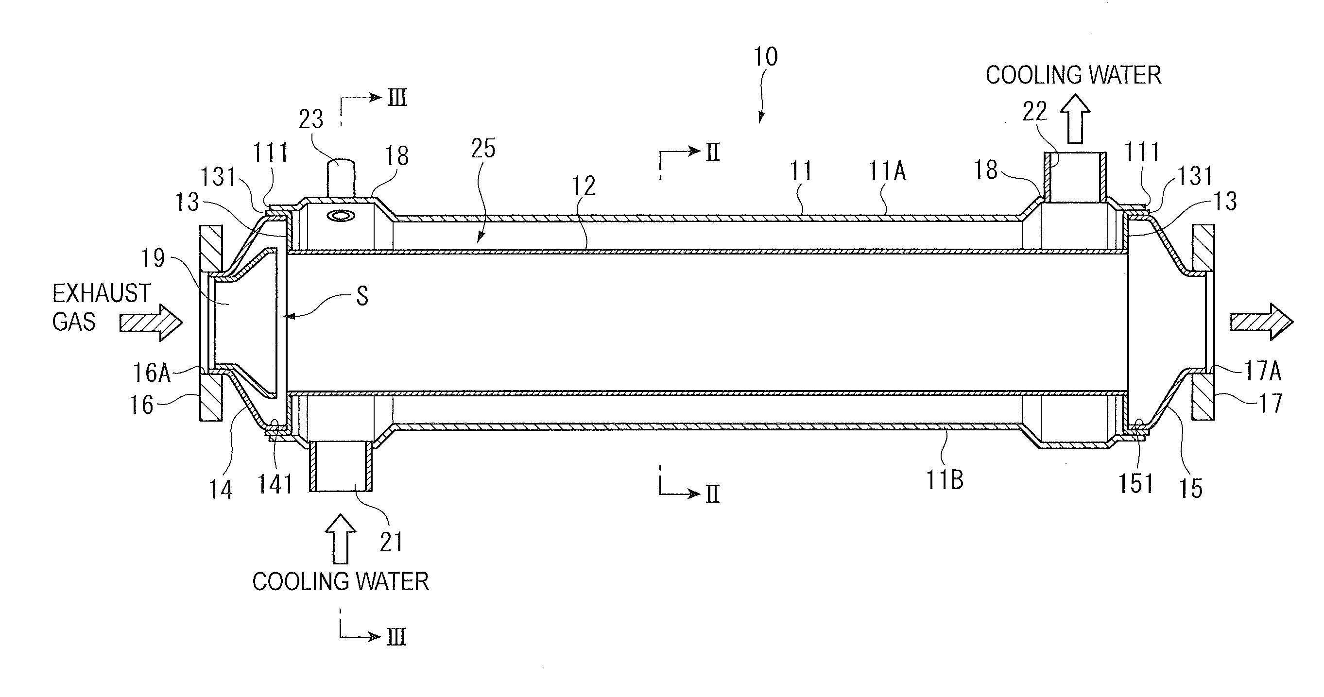
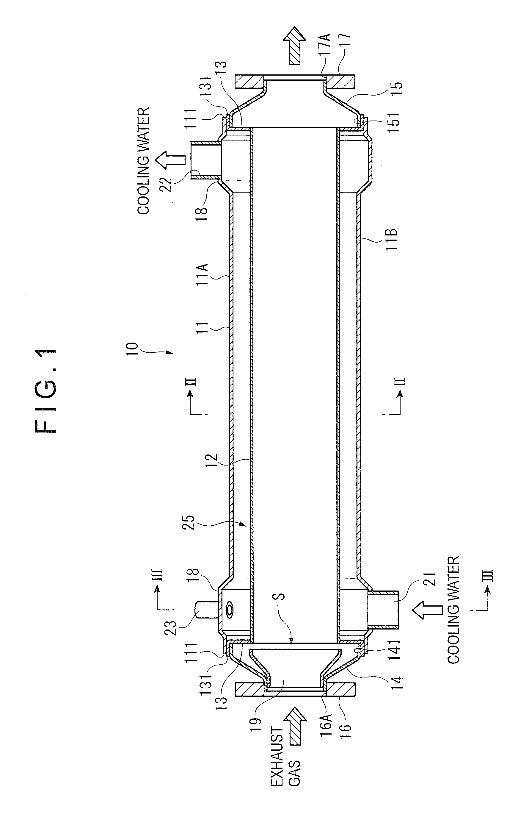
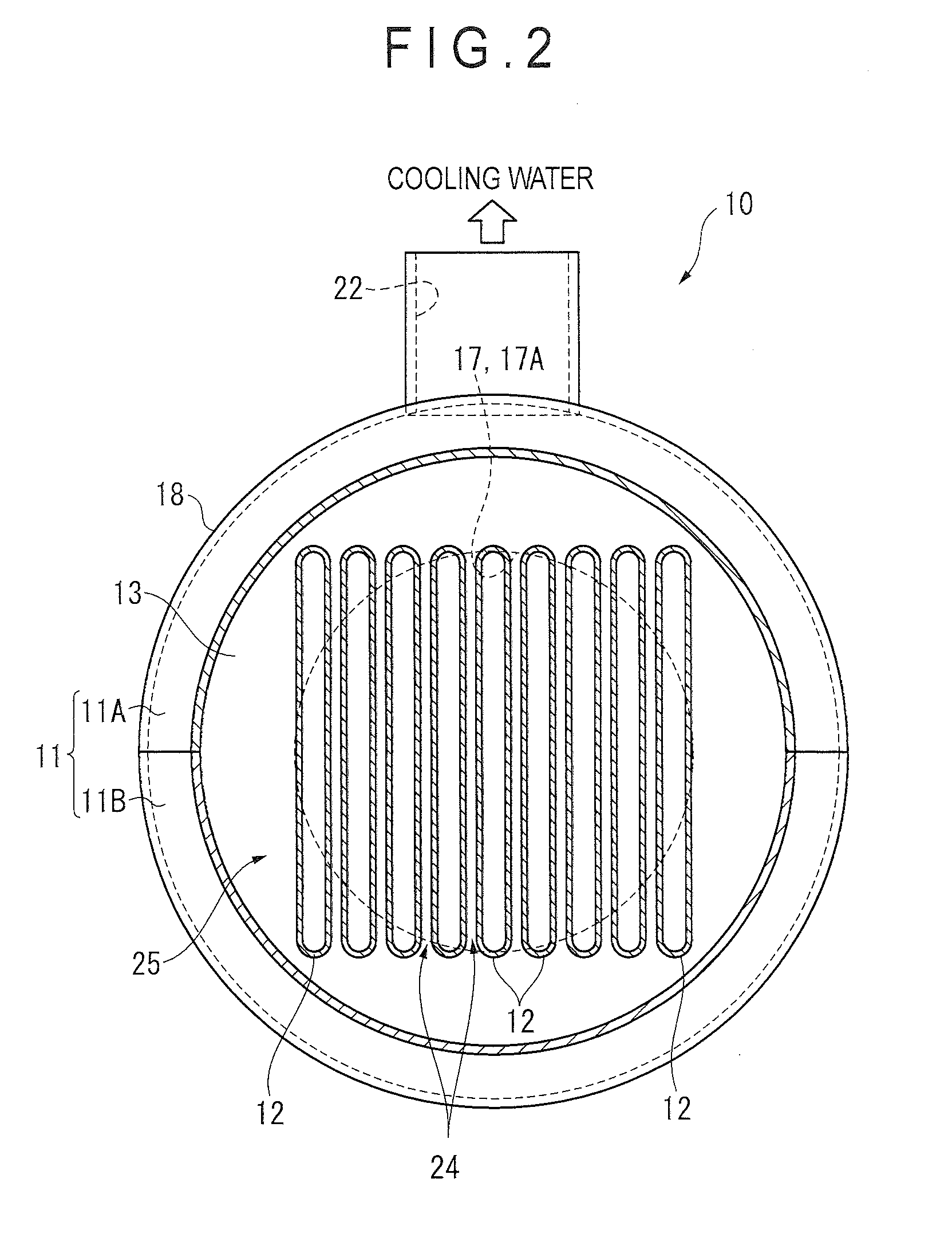
[0033]FIG. 1 is a sectional view of an EGR cooler 10 according to this exemplary embodiment along a flow direction of exhaust gas (see a hatched arrow). FIG. 2 is a sectional view taken along the line II-II in FIG. 1. FIG. 3 is an enlarged view showing a primary part of the EGR cooler 10. FIG. 4 is a view showing components used in the EGR cooler 10 and FIG. 5 is a sectional perspective view thereof In the following description, “front” means the upstream side of a flow of exhaust gas and “rear” means the downstream side. Further, “right and left” means right and left when viewed from the front.

[0034]Referring to FIG. 1, the EGR cooler 10 includes: a cylindrical casing 11; a plurality of flattened tubes 12 for exhaust gas circulation housed in the casing 11; opposed header plates 13 to which the ends of the tubes are bonded; and an inlet tank 14 and an outlet tank 15 bonded...


PUM


Abstract

An EGR cooler includes: a casing in which cooling water flows; a plurality of tubes in which exhaust gas flows, the plurality of tubes being housed in the casing; a header plate to which ends of the plurality of tubes are bonded, the header plate being bonded to an end of the casing; an inlet tank into which the exhaust gas is introduced, the inlet tank being bonded to the end of the casing; and a shielding member being provided in the inlet tank to shield a circumferential wall of the inlet tank from the introduced exhaust gas.

Description

TECHNICAL FIELD[0001]The present invention relates to an EGR (Exhaust Gas Recirculation) cooler.BACKGROUND ART[0002]Some typical EGR systems usable in a diesel engine are provided with an EGR cooler for cooling exhaust gas to be returned to an air-intake side. The EGR cooler includes a plurality of tubes through which exhaust gas passes and a casing (sometimes called as a “shell”) in which these tubes are housed. The casing has a first end that defines an inlet through which cooling water is introduced and a second end that defines an outlet through which the cooling water is discharged.[0003]The casing is formed in a cylindrical shape. An opening of the first end of the casing is provided with an inlet tank into which exhaust gas is introduced and from which the exhaust gas is discharged into the tubes. An end of the second end of the casing is provided with an outlet tank from which the exhaust gas from the tubes is discharged. Both ends of each tube in the casing are fixed to hea...

Claims


Application Information

Patent Timeline
Patent Type & Authority Applications(United States)
IPC IPC(8): F28D7/10
CPCY02T10/121F02M25/0737F02M26/32
Inventor TSUDA, HIROSHIOKUBO, TAISEIFURUHASHI, KAZUOINABA, KEIICHI
Owner KOMATSU LTD
Why Eureka
Try Eureka