Method and Apparatus for Producing High Volumes of Clean Water by Electro Coagulation

a technology of electrocoagulation and high volume, applied in the direction of manufacturing tools, electric circuits, electric circuit machining, etc., can solve the problems of increasing the cost of operation, increasing the maintenance cost and down time of the entire system, and prolonging the life of the plates, so as to reduce or eliminate the need for replacing plates, reduce the need for scaling, and enhance the electrocoagulation process

Inactive Publication Date: 2011-12-22
LATITUDE CLEAN TECH GRP
View PDF9 Cites 17 Cited by
  • Summary
  • Abstract
  • Description
  • Claims
  • Application Information

AI Technical Summary

Benefits of technology

The invention provides that aluminum, iron, polymers, and other material that enhance the electro coagulation process are injected into the influent stream in advance of the reaction chamber. These injected materials can be used with sacrificing and non-sacrificing electrode plates to reduce or eliminate the need to replace plates and can also eliminate or reduce scale.
The invention further provides that the electrode plates can be rounded on the corners and beveled on the edges to increase the reaction on the plates and eliminate surface charges which can concentrate at sharp points.
In addition, the invention provides that the electrode plates are contained in cells or sets formed of alternating positive (anode) plates and negative (cathode) plates. Within a first cell or first set of plates, alternating plates are oppositely charged so that anodes and cathodes face one another and each flow path for effluent through a single cell or set must pass between an anode and a cathode. A second cell or set of plates follows the first set, and the flow path for effluent now extends between electrode plates of the second set. However, the order of the alternating anodes and cathodes is reversed in the second set. Thus, if the flow path in the first set is viewed as having an anode on the right, the flow path in the second set has the anode on the left. Likewise, the position of the cathode is switched from first set to second set along a single flow path. This reversal of field at successive serial lengths of the flow path increased turbulence and reactivity.

Problems solved by technology

The buildup of deposits on metal cathode plates increases generated heat, while the breakdown of the positively charged anode leads to maintenance costs and down time for the entire system, which increases the cost of operation.
The system provides an ability to change the polarity on these positive and negative plates, which extends the life of the plates and results in reduced maintenance.

Method used


Image

  • Method and Apparatus for Producing High Volumes of Clean Water by Electro Coagulation
  • Method and Apparatus for Producing High Volumes of Clean Water by Electro Coagulation
  • Method and Apparatus for Producing High Volumes of Clean Water by Electro Coagulation

Examples


Embodiment Construction

The following detailed description of the invention is merely exemplary in nature and is not intended to limit the invention or the application and uses of the invention. Furthermore, there is no intention to be bound by any theory residing in the preceding background of the invention or the flowing detailed description of the invention.

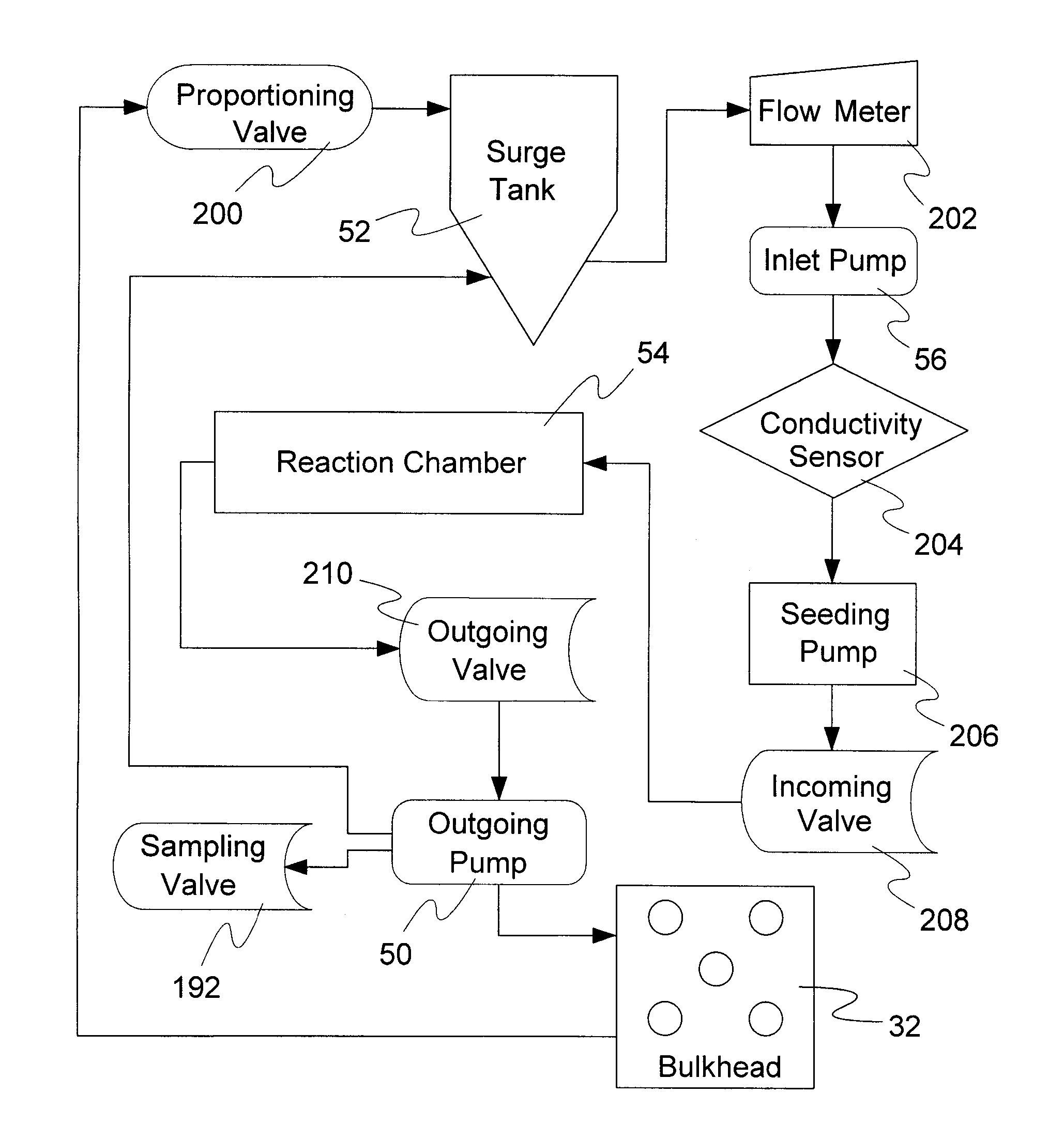
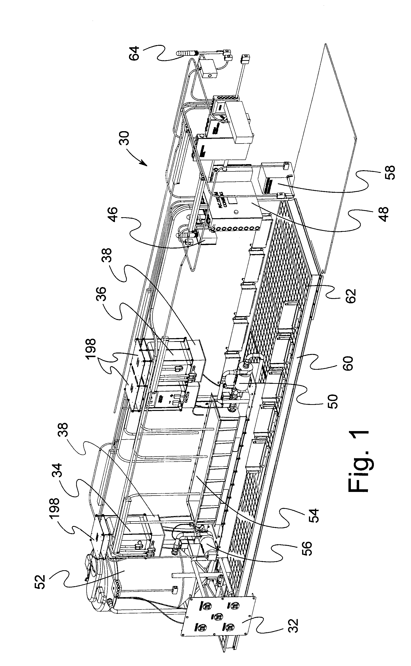
With reference to the drawings, the electro coagulation (EC) system 30, also known as an electro precipitation (EP) system, is suited to treat a stream of fluid influent such as water, which will be referred to as process water, process fluid, or influent. FIG. 1 illustrates the EC system 30 and its major components. Process water is brought into the system through an inlet at main interface system or main disconnect 32, where various streams coming into the system and leaving the system can be managed. The disconnect plate provides a common connection point for incoming clean water needed to flush out the system during scheduled maintenance interval...


PUM

PropertyMeasurementUnit
residence timeaaaaaaaaaa
reaction rateaaaaaaaaaa
timeaaaaaaaaaa

Abstract

In an electrolytic apparatus for removing contaminants from water, a set (110) of spaced apart conductive electrodes (40) in a reaction chamber (54, 112, 114), is arranged in oppositely charged groups of first and second interleaved electrodes with flow paths between them. Non-conductive turbulence inducers (158, 168) on the faces of electrodes (40) are applied to water in the flow paths. One variety is modular elements (1 58) with stepped increases in width to present a narrow leading edge in the direction of flow. Another variety is a continuous set of wave guides (168) bordering the flow path. Electrodes (40) are selectively powered in patterns creating turbulence, with effective patterns including a first and last electrode powering pattern and a mini-cell electrode powering pattern.

Description

BACKGROUND OF INVENTION1. Field of the InventionThe invention generally relates elements used in electrical and wave energy chemistry. More specifically, the invention relates to electrolytic apparatus composed of electrodes with an electrode supporting means consisting of a dielectric gasket or spacer. In a further aspect, the invention relates to an electrolytic apparatus and method that employ parallel plate electrodes to form plural separate treatment chambers or zones, with a feeding or withdrawing means providing a flow of liquid to be treated to the cells. The invention discloses apparatus and method for water purification and with the ability to control and monitor variables needed to achieve optimal water purification results using minimal power consumption.2. Description of Related Art Including Information Disclosed Under 37 CFR 1.97 and 1.98Electro coagulation is the process of introducing electricity to a process fluid such as water to induce a chemical reaction. It is ...

Claims


Application Information

Patent Timeline
Patent Type & Authority Applications(United States)
IPC IPC(8): C25B15/00C02F1/461
CPCC02F1/46109C02F1/463C02F2201/4611C02F2201/4617C02F2301/024C02F2209/05C02F2209/06C02F2209/40C02F2209/42C02F2209/006
Inventor GILMORE, F. WILLIAMRENK, RUSSELL
Owner LATITUDE CLEAN TECH GRP
Why Eureka
Try Eureka