Lighting apparatus and method of manufacturing the lighting apparatus

a technology of lighting apparatus and lighting system, which is applied in the direction of lighting and heating apparatus, lighting support devices, fixed installations, etc., can solve the problems of high durability, impact resistance, and failure to provide a configuration for obtaining the complete waterproofing property, and achieve the desired illuminance or illumination area, strong, and sufficient durability and impact resistance

Active Publication Date: 2011-12-22
SUZUDEN CORP +1
View PDF8 Cites 17 Cited by
  • Summary
  • Abstract
  • Description
  • Claims
  • Application Information

AI Technical Summary

Benefits of technology

[0024]A substrate on which a light-emitting diode is mounted is connected to an electric wire. Synthetic resin material is used to closely cover the electric wire, the substrate, and the light-emitting diode in an integrated manner. Thus, the lighting apparatus can have a complete waterproofing property. Furthermore, the light-emitting diode, the substrate on which the light-emitting diode is mounted, and the light-emitting diode are closely covered by synthetic resin material, thus providing sufficient durability and impact resistance. Furthermore, since there is no space among the respective components, such a pressure resistance can be obtained that prevents water intrusion or the damage or deformation by a water pressure even in a pool or seawater for example. Therefore, such a lighting apparatus can be provided that can be used in a construction site, aplastic greenhouse, a poultry house, a pool, or seawater without the risk of damage or electrical leakage.
[0025]The synthetic resin material of the light-emitting diode-mounted-side of the substrate on which the light-emitting diode is mounted is translucent resin material to form an illumination section. Thus, all of the electric wire, the substrate, the light-emitting diode, and the illumination section are formed in an integrated manner by synthetic resin material. The translucent resin material emits light like a conventional light bulb, providing a sufficient illumination effect.
[0026]The illumination section is formed to have a planar shape, a convex shape, a convex lens-like

Problems solved by technology

The resin filled in the housing is merely used to fix the light-emitting diode module, thus failing to provide a configuration for obtaining the complete waterproofing property, high durability, and impact r

Method used


Image

  • Lighting apparatus and method of manufacturing the lighting apparatus
  • Lighting apparatus and method of manufacturing the lighting apparatus
  • Lighting apparatus and method of manufacturing the lighting apparatus

Examples


first embodiment

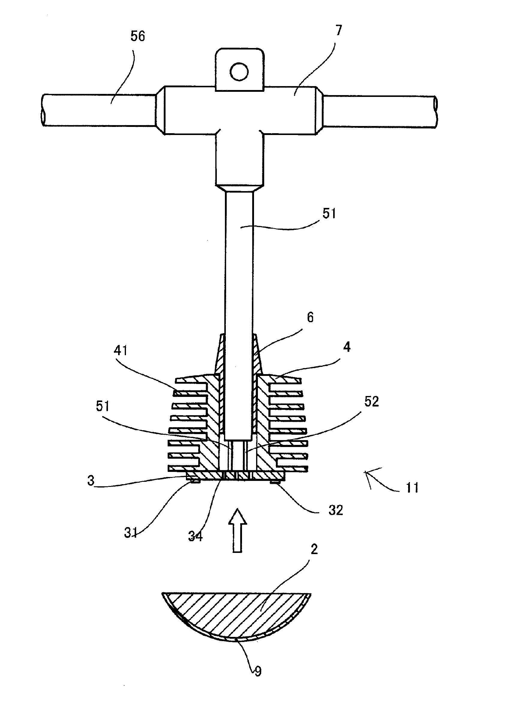
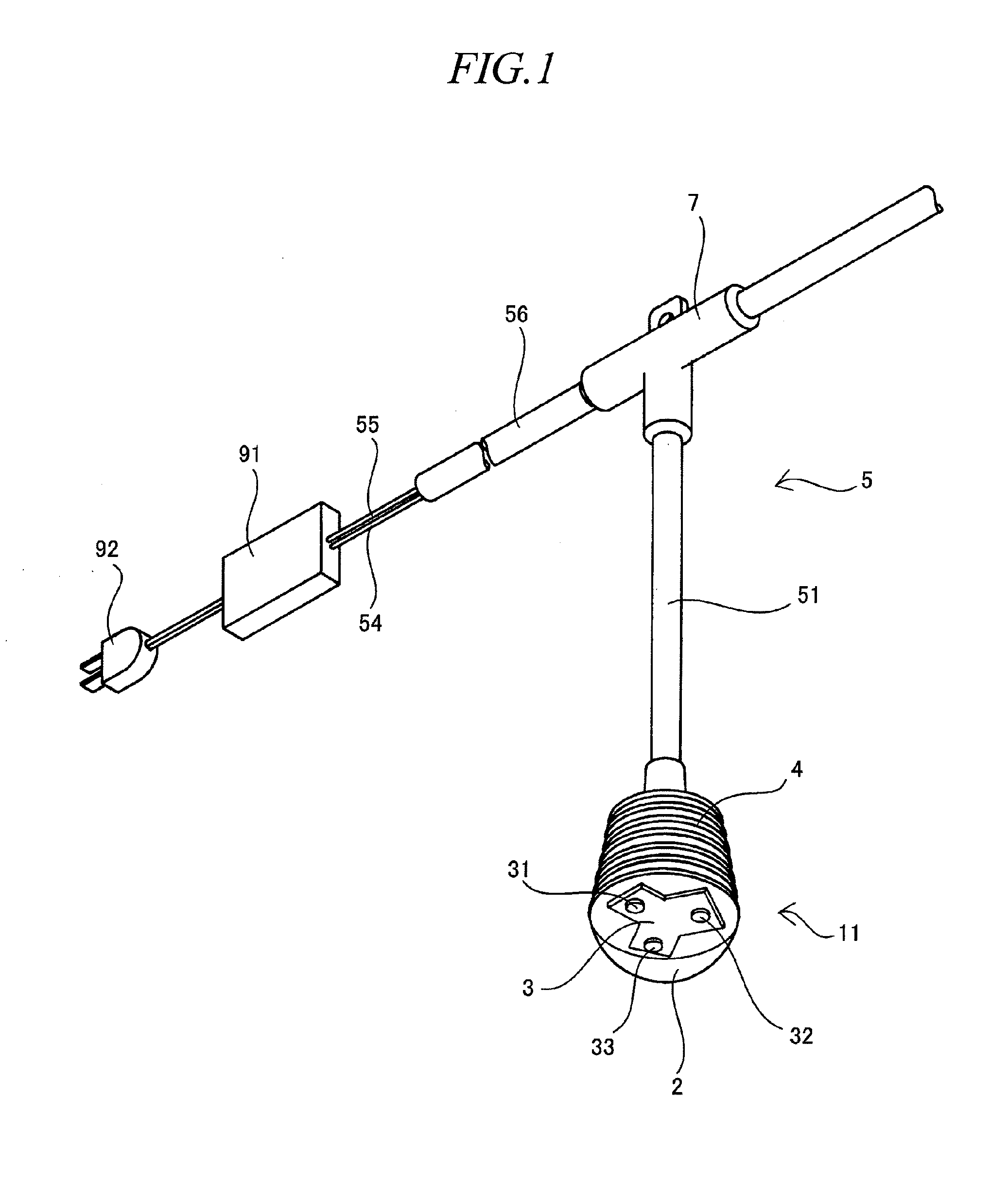
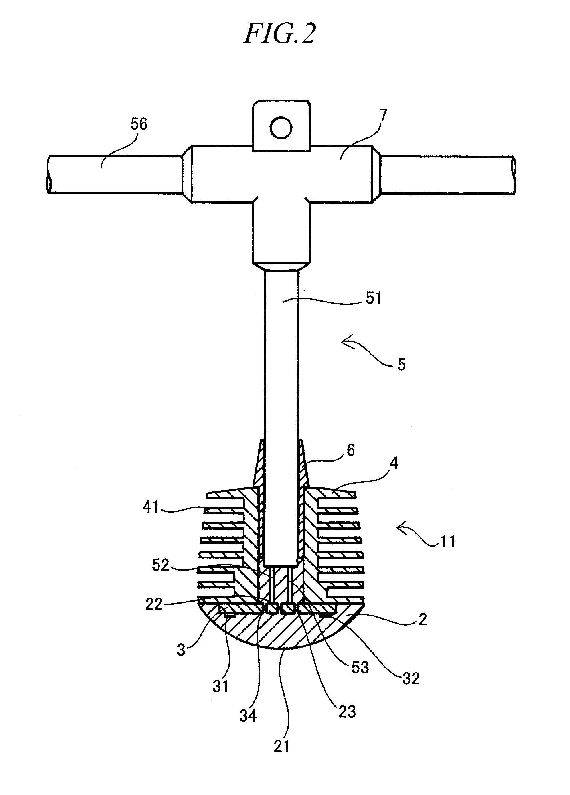
[0097]According to one of the methods of manufacturing the lighting apparatus of the first embodiment, the substrate 3 on which the light-emitting diodes 31, 32, and 33 are mounted, as well as the connecting part of the substrate 3 and the electric wires 52 and 53 are placed in a mold. Then, the mold is filled with the molten translucent resin material 2 for molding. Then, the heatsink 4 is provided at the periphery thereof to cure the translucent resin material 2 to thereby closely cover the respective members in an integrated manner and to form the illumination section 21. At least the side at which the light-emitting diodes 31, 32, and 33 are mounted is filled with the translucent resin material 2. Thus, an opposite side of the side at which the light-emitting diodes 31, 32, and 33 are mounted may be filled with non-translucent resin material for molding.

[0098]According to another manufacture method, the substrate 3 on which the light-emitting diodes 31, 32, and 33 are mounted as...

second embodiment

[0106]According to one of the methods of manufacturing the lighting apparatus of the second embodiment, the substrate 3 on which the light-emitting diodes 31, 32, and 33 are mounted as well as the electric wires 52 and 53 connected to the substrate 3 are placed in a mold. Then, the mold is filled with the molten translucent resin material 2 and is molded. Then, the heatsink 4 is provided at the periphery thereof to cure the translucent resin material 2 to thereby closely cover the respective members in an integrated manner and to form the illumination section 21. At least the side at which the light-emitting diodes 31, 32, and 33 are mounted is filled with the translucent resin material 2. Thus, an opposite side of the side at which the light-emitting diodes 31, 32, and 33 are mounted may be filled with non-translucent resin material for molding.

[0107]According to another manufacture method, the substrate 3 on which the light-emitting diodes 31, 32, and 33 are mounted as well as the...

third embodiment

[0116]According to one of the methods of manufacturing the lighting apparatus of the third embodiment, the substrate 3 on which the light-emitting diodes 31, 32, and 33 are mounted, as well as the connecting part of the substrate 3 and the electric wires 52 and 53 are placed in a mold. Then, parts for forming the heatsink section 42 are mixed with alumina powders. These parts are molded by the translucent resin material 2 to thereby closely form the respective members in an integrated manner and to form the illumination section 21 and the heatsink section 42.

[0117]According to another manufacture method, the substrate 3 on which the light-emitting diodes 31, 32, and 33 are mounted, as well as the connecting part of the substrate 3 and the electric wires 52 and 53 are placed in a mold. Then, parts for forming the heatsink section 42 are mixed with alumina powders. These parts are subjected to injection molding by the translucent resin material 2 to thereby closely form the respective...


PUM


Abstract

The invention of the present application provides a lighting apparatus that has superior waterproofing property, durability, impact resistance, and pressure resistance and that can be used in various places such as a construction site, a plastic greenhouse, a poultry house, water, or seawater.
The invention of the present application provides a lighting apparatus in which electric wires are connected to a substrate 3 on which light-emitting diodes 31, 32, and 33 are mounted and synthetic resin material is used to closely cover the electric wires 52 and 53, the substrate 3, and the light-emitting diodes 31, 32, and 33 in an integrated manner.

Description

TECHNICAL FIELD[0001]The present invention relates to a lighting apparatus and the manufacture method thereof. In particular, the present invention relates to a lighting apparatus that uses a light-emitting diode light source and that is superior in the waterproofing property and the durability for example.BACKGROUND ART[0002]Conventionally, a lighting apparatus used in a construction site, a plastic greenhouse, or a poultry house for example has been configured so that a light bulb is screwed with a socket that is electrically connected to a power source via a cable. The construction waterproof socket disclosed in Patent Publication 1 has sufficient waterproofing property and durability for a socket. However, there has been a demand for the complete waterproofing property of the entire lighting apparatus and further-improved durability and impact resistance.[0003]In recent years, the use of a light-emitting diode element as a light source for a lighting apparatus has been known bec...

Claims


Application Information

Patent Timeline
IPC IPC(8): H01L33/58
CPCF21S8/068F21V21/008F21V31/00F21V31/04F21V29/767F21V29/85F21V29/86F21V29/89F21S4/10F21Y2115/10F21K9/20
Inventor KAWASHIMA, HIROAKI
Owner SUZUDEN CORP
Why Eureka
Try Eureka