
Handheld rotationally rechargeable electronic apparatus

Active Publication Date: 2011-12-22
BUDZISZEK BOBBY LEE +1
View PDF7 Cites 5 Cited by
  • Summary
  • Abstract
  • Description
  • Claims
  • Application Information

AI Technical Summary

Benefits of technology

[0007]A further object of the invention is to provide apparatus of this nature whose battery can be recharged very easily, even by technically unsophisticated users.
[0013]While the generator and regulator circuit may be included in the electronic device itself, preferably they are present in a case that protectively encloses the device. In any event, as will be described in detail later, the generator is of a flat pancake-type construction that projects or protrudes a minimal distance from the device so that it does not add appreciably to the overall footprint or profile of the device by itself. Also, as will be seen, the regulator circuit adapts or conditions the output signal from the generator to suit the power requirements of the particular device so that by spinning the device, the device's batteries may be recharged in a minimum amount of time.
[0014]Thus, the batteries of the present apparatus can be recharged, even when outside power is not available, enabling a user to operate the device whenever that becomes necessary or desirable.

Problems solved by technology

The main disadvantage of such battery powered devices is that external power to recharge the batteries is not always available.
For example, one of the biggest markets for cell phones is in so-called third world countries, many of which do not have a good network of telephone landlines.
However, those countries are just as likely to not have a reliable electrical network for distributing power to people's homes and businesses.
Therefore, in order to recharge the batteries of their cell phones, users are often required to so do at a central location that does have electrical power, which is an inconvenience to the users.

Method used


Image

  • Handheld rotationally rechargeable electronic apparatus
  • Handheld rotationally rechargeable electronic apparatus
  • Handheld rotationally rechargeable electronic apparatus

Examples


Embodiment Construction

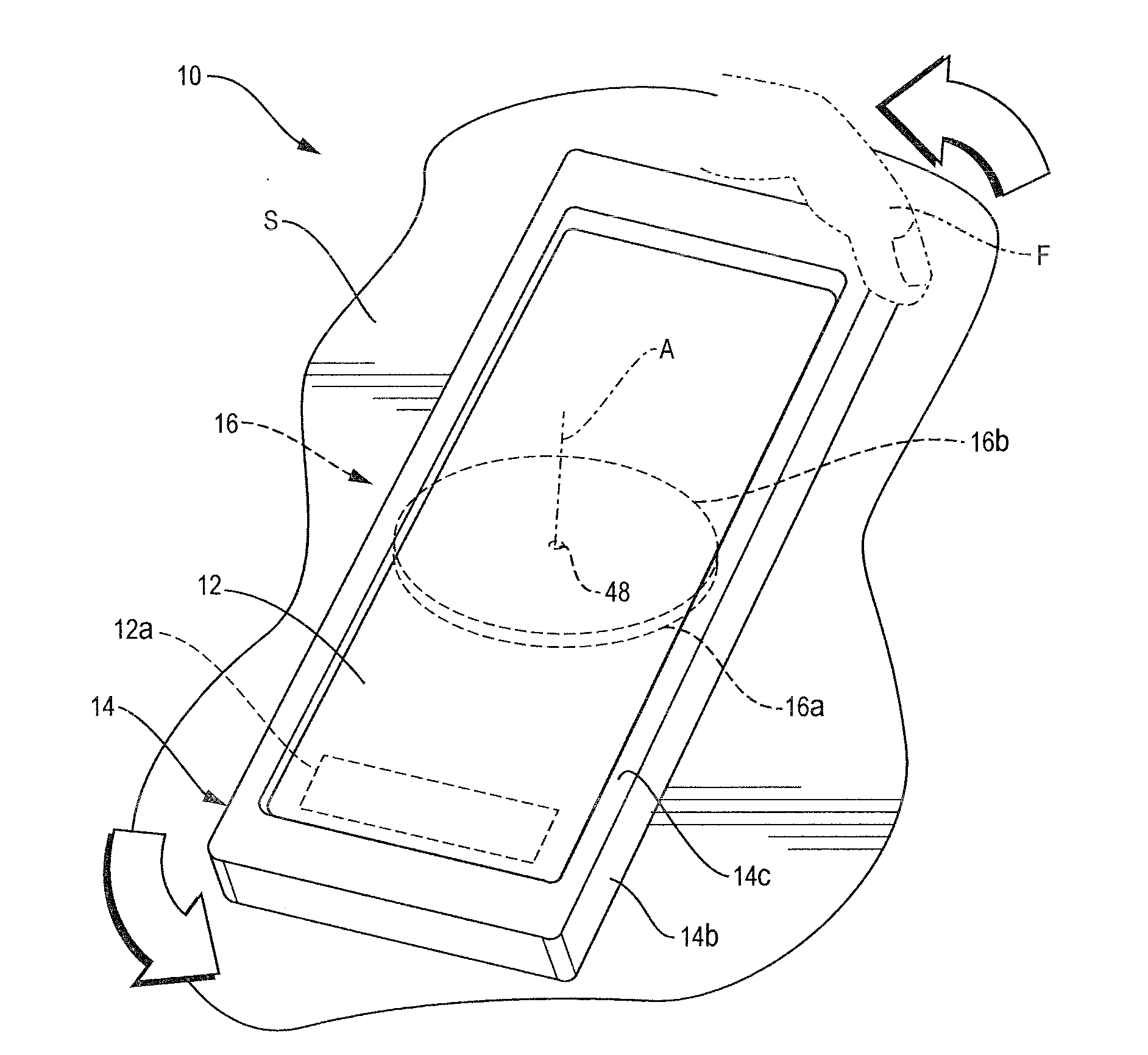
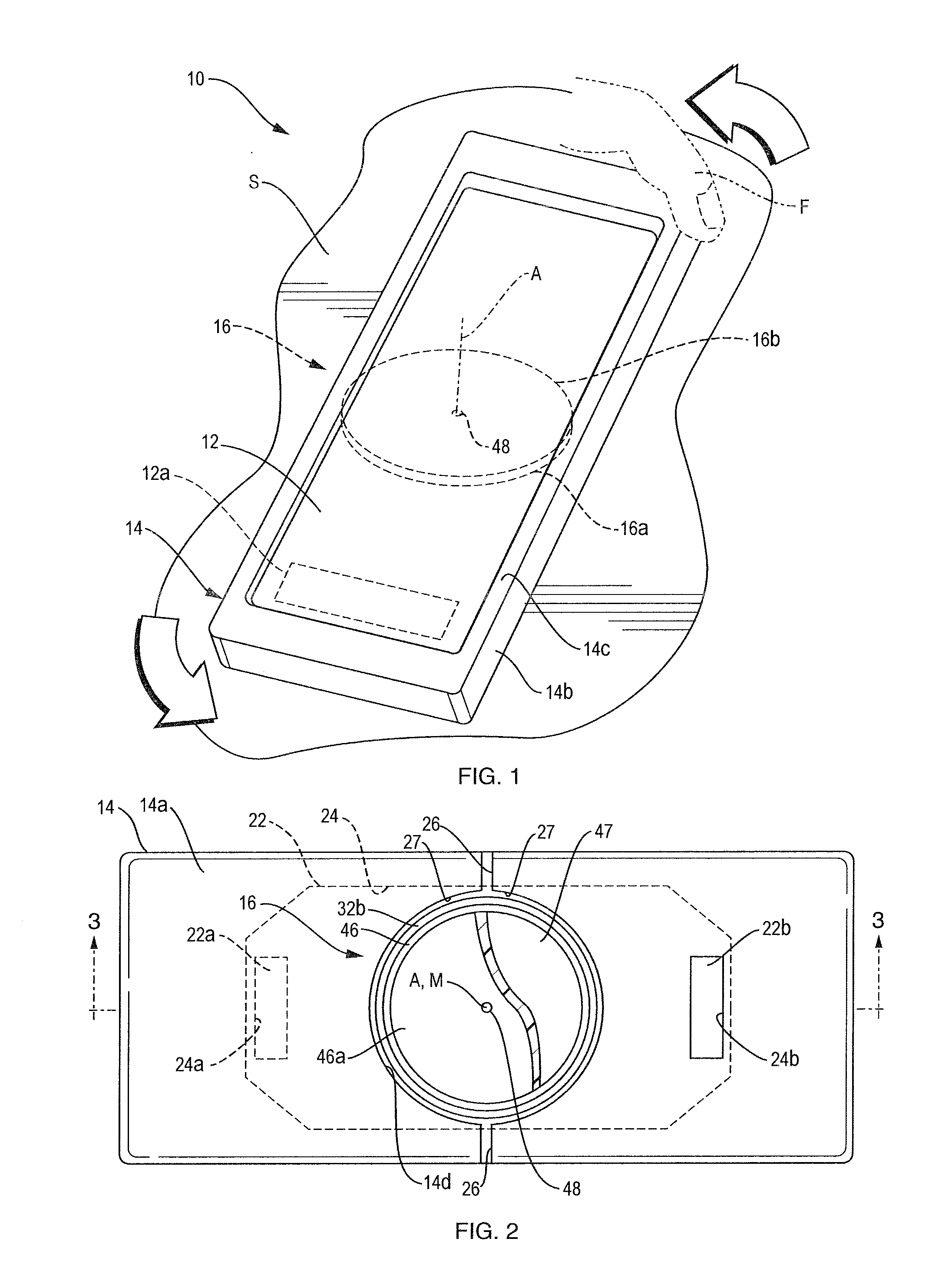
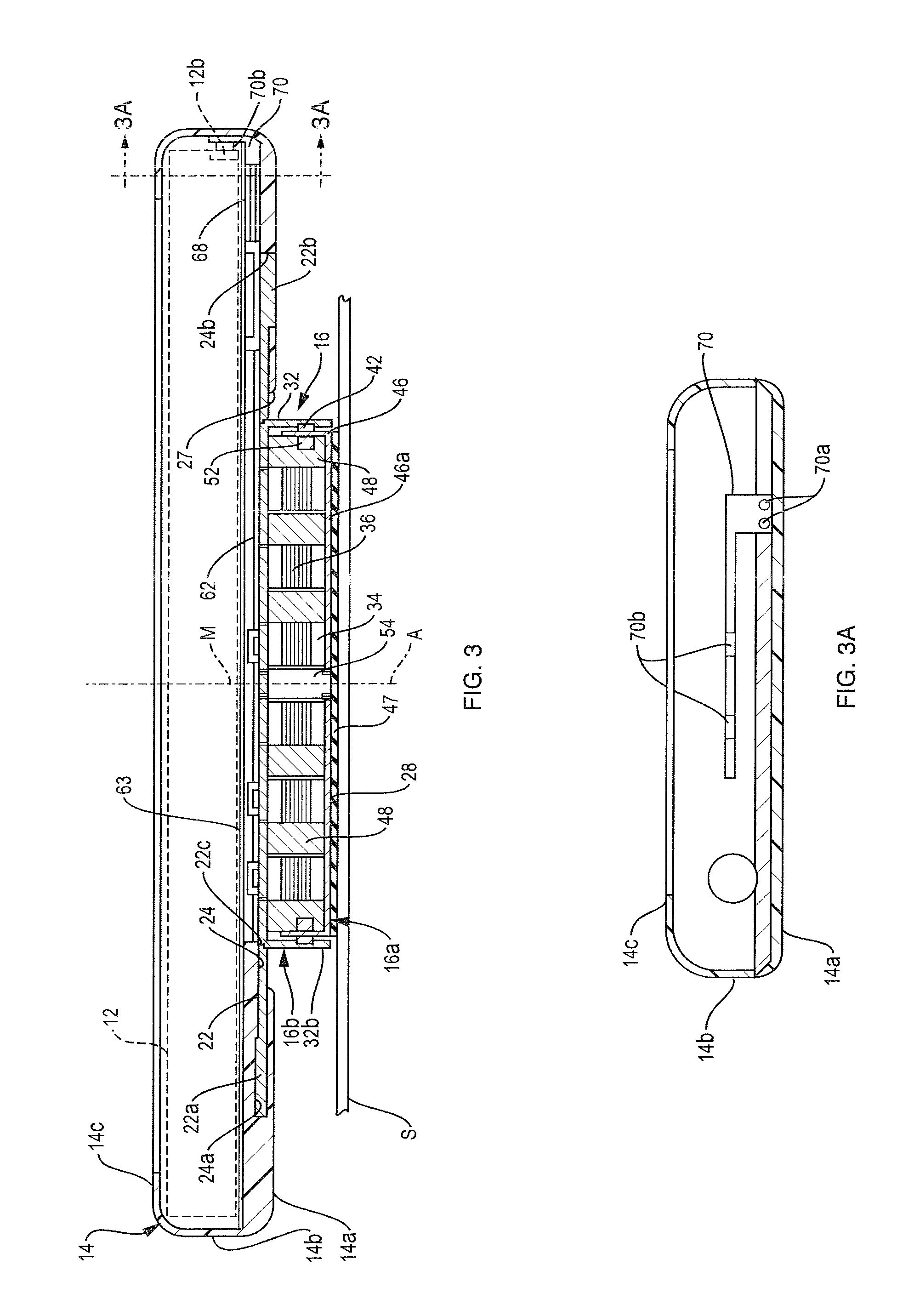
[0023]Referring to FIG. 1 of the drawings, the present apparatus, shown generally at 10, comprises a small electrical or electronic device 12 which is normally powered by one or more internal rechargeable batteries 12a. Device 12 may be any one of a number of conventional handheld or portable electrical or electronic devices, some of which are identified in the background section of this application. The illustrated device 12 happens to be a cell phone that is protectively enclosed in a flexible case 14 which is designed to expose the phone's display screen and to allow access to the phone's various controls and connector ports. These ports include a standard input port 12b (FIG. 3) normally used to recharge the device's battery 12a from a remote power source.

[0024]In accordance with the invention, a flat pancake-shaped generator shown generally at 16 is secured by case 14 to the back of device 12. Generator 16 includes a rotor 16b which is fixed to case 14 and a stator 16a which pr...


PUM


Abstract

A rotationally rechargeable electrical apparatus includes an electronic device with a back, a center of mass and a battery. An electrical generator at the back of the device has a rotor secured to the device and a stator having a flat contact surface extending parallel to the back of the device. The rotor and stator are rotatably connected together so that they can rotate relatively about an axis that extends perpendicular to the contact surface and passes through the center of mass. A voltage regulating circuit is connected electrically between the generator and the battery so that when the apparatus is placed on a support so that the contact surface frictionally engages the support and the device is spun about the axis, the generator produces an electrical output that is conditioned by the regulator circuit to charge the battery.

Description

[0001]This invention relates to a handheld battery-powered electric or electronic device. It relates especially to such a device whose batteries may be recharged without requiring an external power source.BACKGROUND OF THE INVENTION[0002]Small handheld or portable battery-powered devices are becoming ever more prevalent. These devices include cell phones, cameras, electronic games, radios, TVs, flashlights, GPS, receivers, recording and playback devices, etc. In many cases, such devices are powered by one or more batteries of the rechargeable type.[0003]The main disadvantage of such battery powered devices is that external power to recharge the batteries is not always available. For example, one of the biggest markets for cell phones is in so-called third world countries, many of which do not have a good network of telephone landlines. However, those countries are just as likely to not have a reliable electrical network for distributing power to people's homes and businesses. Theref...

Claims


Application Information

Patent Timeline
IPC IPC(8): H02J7/14F03G5/06
CPCH02J7/32
Inventor BUDZISZEK, BOBBY LEEMCMASTER, COLLIN JAMES
Owner BUDZISZEK BOBBY LEE
Learn More