Method and electronic operating device for operating a gas discharge lamp and projector

a technology of electronic operating device and gas discharge lamp, which is applied in the direction of projectors, light sources, instruments, etc., can solve the problems of inability to meet the requirements of high-pressure discharge lamps, the ratio between current intensity and light level is not necessarily linear, and the electronic operating device for these lamps is more expensive. achieve the effect of maximum compatibility and good operational reliability

Inactive Publication Date: 2011-12-22
OSRAM GMBH
View PDF8 Cites 5 Cited by
  • Summary
  • Abstract
  • Description
  • Claims
  • Application Information

AI Technical Summary

Benefits of technology

[0017]In a first form of the method, the commutation pattern is generated in this case by omitting commutation at those commutation points at which no commutation is to occur. This represents the simplest embodiment, and also offers good operational reliability since only those commutations are carried out that are absolutely necessary.
[0018]In a second form of the method, the commutation pattern is generated by allowing commutation nonetheless to occur at those commutation points at which no commutation is to occur, said commutation however being reversed again by means of a further commutation following immediately thereupon. This procedure is also referred to as double commutation. This procedure offers the advantage of maximal compatibility with existing switching topologies, which cannot carry out the first form of the method due to technical restrictions.

Problems solved by technology

In terms of operation, high pressure discharge lamps are more difficult to handle than low pressure discharge lamps in this case, and the electronic operating devices for these lamps are therefore more expensive.
Furthermore, depending on the light sources used in the lighting apparatus, the ratio between current intensity and light level is not necessarily linear.
Consequently, a change of the current intensity also results in a change of the spectrum locus of the light of the light source, and hence in a change of the color temperature of the display system.
Furthermore, the color depth of the display system is limited by the minimal ON-time of a pixel.
However, this usually results in noise which is visible to a human observer.
However, a mechanical screen requires space in the lighting apparatus or the display system, increases the weight of the lighting apparatus or the display system, and also represents an additional potential source of interference.
High pressure discharge lamps such as those used in such display systems can also be operated in a dimmed mode, though the dimmed operating mode raises problems with regard to the electrode temperature and the arc root in the high pressure discharge lamp.
The arc root is generally problematic when alternating current is used for operation of a gas discharge lamp.
This change is accompanied by an interruption in the light output, which is often visible and can be perceived as flickering.
The variation or distortion of the electrodes over the entire service life represents a significant problem of high pressure discharge lamps.
Moreover, there is a risk of producing electrode tips that are not arranged in the center of the relevant electrode.
If a plurality of electrode tips of approximately equal validity are present on an electrode, this can result in arc jumping and hence to flickering of the lamp.
In certain cases, the electrode tips can grow unevenly, such that the electric arc is no longer arranged centrally in the burner vessel, but is shifted axially.
This likewise degrades the optical image of the overall system.
By contrast, the fissuring results in an increase of the original electrode separation and therefore also affects the lamp voltage.
As this increases proportionally relative to the separation, it can result in premature service life shutdown, since this usually occurs when the lamp voltage exceeds a predetermined threshold value.
In summary, this results in a reduction in the lamp service life and in the quality of the light emitted from the lamp.
The prior art does not currently disclose any solutions to these problems.
Since electronic operating devices are naturally configured for a specific maximum current, this results in problems.

Method used


Image

  • Method and electronic operating device for operating a gas discharge lamp and projector
  • Method and electronic operating device for operating a gas discharge lamp and projector
  • Method and electronic operating device for operating a gas discharge lamp and projector

Examples


first embodiment

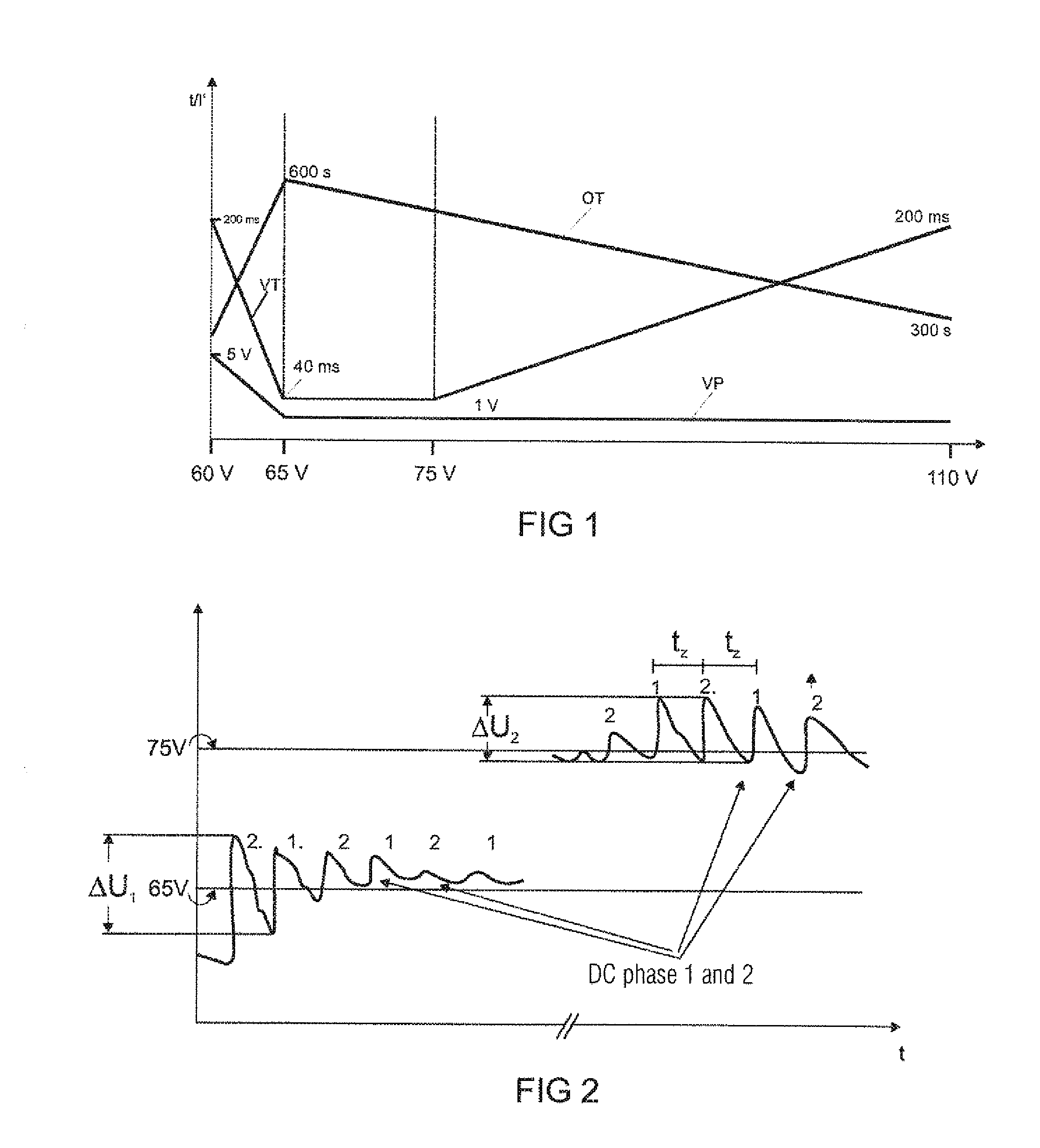
[0045]FIG. 1 shows a graph illustrating the relationship between the duration of a DC voltage phase (curve VT) which is applied to the gas discharge lamp, a separation between two DC voltage phases (curve OT), a voltage change in the DC voltage phase (curve VP), and the lamp voltage for a first embodiment of the operating method according to the invention. The curve VT therefore illustrates the length of the DC voltage phase as a function of the lamp voltage. The curve OT illustrates the separation (also referred to in the following as the off-time) between two DC voltage phases, i.e. the time before a DC voltage phase is re-applied to the gas discharge lamp. Since the electrode more or less fuses when a DC voltage phase is applied, and the electrode separation and hence the lamp voltage increases, this is greater after the DC voltage phase than before the DC voltage phases. The curve VT then shows the change of the lamp voltage during the DC voltage phase as a function of the lamp ...

second embodiment

[0055]In a second embodiment of the method, the length of the DC voltage phases is not controlled via a characteristic curve, instead the length of the DC voltage phases is regulated via the lamp voltage in the DC voltage phase itself. The above described curve VP shows the maximal voltage change of the lamp voltage in the DC voltage phase as a function of the lamp voltage. The voltage change is measured during the DC voltage phase. For this, the circuit arrangement which executes the method features a measuring apparatus, which can measure the lamp voltage before the DC voltage phase, and particularly the change of the lamp voltage during a DC voltage phase. The change of the lamp voltage during the DC voltage phase is evaluated in respect of an interrupt criterion, and the DC voltage phase is terminated when the interrupt criterion is reached. FIG. 2 shows a graph which illustrates the method of the second embodiment. There are two threshold values, the second embodiment being exe...

third embodiment

[0069]In a third embodiment of the method, a continuous adaptation of the operating frequency takes place as a function of the lamp voltage. The method can be operated in various forms in this case. In a first form of the third embodiment, as illustrated in FIG. 6a, the operating frequency is changed in discrete steps depending on the lamp voltage. In this case, the frequency becomes higher as the lamp voltage increases. Since a commutation can only take place at specific times due to various outline conditions in the overall system, the operating frequency can only assume a limited number of frequency values. If the gas discharge lamp is operated in a video projector including a color wheel, for example, the operating frequency of the gas discharge lamp can only be commutated if the color wheel is in a position at which a change from one color segment to the next is taking place at the time. Due to the constant rotational speed of the color wheel, which in turn depends on the image...


PUM


Abstract

A method for operating a gas discharge lamp may include; the gas discharge lamp is operated using an intermittently constant lamp current, whose time-relative average value of the frequency is predetermined by the lamp voltage of the gas discharge lamp in the steady state, wherein the lamp current has predefined commutation points in the temporal course, and a commutation for generating a commutation pattern can take place at these commutation points, wherein the time-relative average value of the frequency of the lamp current is adjusted by means of a variation of the commutation pattern.

Description

TECHNICAL FIELD [0001]The invention relates to a method and an electronic operating device for operating a gas discharge lamp, the gas discharge lamp being operated using a square-wave lamp current. The invention further relates to a projector which includes such an operating device.PRIOR ART [0002]In recent times, use of gas discharge lamps instead of incandescent bulbs is growing as a result of their high efficiency. In terms of operation, high pressure discharge lamps are more difficult to handle than low pressure discharge lamps in this case, and the electronic operating devices for these lamps are therefore more expensive.[0003]High pressure discharge lamps are usually operated by means of a low-frequency square-wave current, also known as intermittent direct current operation. In this case, an essentially square-wave current having a frequency of usually 50 Hz to several kHz is applied to the lamp. The lamp commutates with each oscillation between positive and negative voltage...

Claims


Application Information

Patent Timeline
Patent Type & Authority Applications(United States)
IPC IPC(8): H05B41/36G03B21/14
CPCH05B41/2928
Inventor BRUECKEL, MARTINDIERKS, BARBELFLESCH, PETERKROELL, JOSEF
Owner OSRAM GMBH
Why Eureka
Try Eureka