Light-water reactor fuel assembly (alternatives), a light-water reactor, and a fuel element of fuel assembly

a fuel element and light-water reactor technology, applied in the direction of nuclear reactors, greenhouse gas reduction, etc., can solve the problems of not having adequate fossil fuel resources, a considerable threat to the world security, and the proliferation of materials that can be used in nuclear weapons, so as to facilitate the placement of seed fuel elements.

Active Publication Date: 2011-12-22
THORIUM POWER
View PDF6 Cites 12 Cited by
  • Summary
  • Abstract
  • Description
  • Claims
  • Application Information

AI Technical Summary

Benefits of technology

[0034]The fuel assembly in this embodiment, just like the assembly in the first embodiment, contains a channel that has a square cross-sectional shape and that separates the seed region fuel elements from the blanket region fuel elements. Here, 16 guide tubes are located inside the channel, while 8 are located outside it in such a manner as to match the position of the 24 control rods of a 17×17 fuel assembly of a nuclear reactor of the PWR type, thereby ensuring their interchangeability. The seed region's lower nozzle is also connected to the channel, to which a supporting frame structure is attached for the purpose of securing the seed fuel elements. In addition, a guiding grid is attached to the upper section of the channel in order to facilitate the placement of the seed fuel elements that makes their free axial movement possible.

Problems solved by technology

Many countries that do not have adequate fossil fuel resources primarily rely on nuclear power to generate electricity.
Despite the fact that safety is unequivocally the principal issue surrounding the design and operation of nuclear reactors, another key issue includes of the danger of the proliferation of materials that can be used in nuclear weapons.
This is especially true for countries with unstable governments, the possession of nuclear weapons by which might pose a considerable threat to the world security.
A similar security problem also exists relative to the enormous stockpiles of weapons-grade plutonium that are created in the United States of America (USA) and the countries of the former Union of Soviet Socialist Republics (USSR) when nuclear weapons were dismantled.
Another problem associated with the operation of conventional nuclear reactors stems from the ongoing need for long-lived radioactive waste disposal, as well as the rapid depletion of world resources of natural uranium raw materials.
Furthermore, both reactors mentioned above are nonproliferative in the sense that neither the initially charged fuel nor the fuel discharged at the end of each fuel cycle is suitable for making nuclear weapons.
And a small quantity of nonproliferative enriched uranium is added to the breeding region, within which the U-238 component is homogeneously mixed with the left over U-233 at the end of the breeding cycle and “denatures” the U-233 (alters its natural properties), as a result of which it becomes unsuitable for making nuclear weapons.
Unfortunately, neither of the reactor designs cited above is truly “nonproliferative.” In particular, it was discovered that both these designs result in a level of proliferative plutonium formation in the seed region that exceeds the minimum possible level.
The use of a round seed region with an internal or central breeding region and an external encircling breeding region cannot ensure the operation of a reactor as a “nonproliferative” reactor, since the thin round seed region has a correspondingly small “optical thickness”, resulting in the fact that the seed region (of neutrons) spectrum will be dominant over the considerably harder spectrum of the internal and external breeding regions.
Research has shown that the preferred moderator / fuel ratio values, specified in these international applications, are too high in the seed regions and too low in the breeding regions.
The foregoing core designs were also not especially efficient when nonproliferative enriched uranium was used in the seed region fuel elements.
The reactor disclosed in application WO 93 / 16477 also requires a complicated reactor mechanical control circuit that makes it unsuitable for re-equipment of a conventional reactor core.
Likewise, the core of the reactor disclosed in application WO 85 / 01826 cannot be easily transferred to a conventional core, since its design parameters are not compatible with those of a conventional core.
Finally, both foregoing reactor designs were specially conceived for burning nonproliferative enriched uranium with thorium and are not suitable for the use of a large quantity of plutonium.
Accordingly, neither of these designs ensures the resolution of the problem of the stored accumulated plutonium.
However, the seed-and-blanket regions employed in this reactor are not suitable for use in existing light-water reactors of the PWR type cited above (for example, the AP-1000, the EPR, etc.).
However, other than indicating the shape of the assembly's cross-section, the description for the patent cited above does not contain information on the assembly structural variations that would facilitate its installation in an existing light-water reactor of the PWR type (for example, the AP-1000, the EPR, etc.) without making changes of any kind in the reactor's design.

Method used


Image

  • Light-water reactor fuel assembly (alternatives), a light-water reactor, and a fuel element of fuel assembly
  • Light-water reactor fuel assembly (alternatives), a light-water reactor, and a fuel element of fuel assembly
  • Light-water reactor fuel assembly (alternatives), a light-water reactor, and a fuel element of fuel assembly

Examples


first embodiment

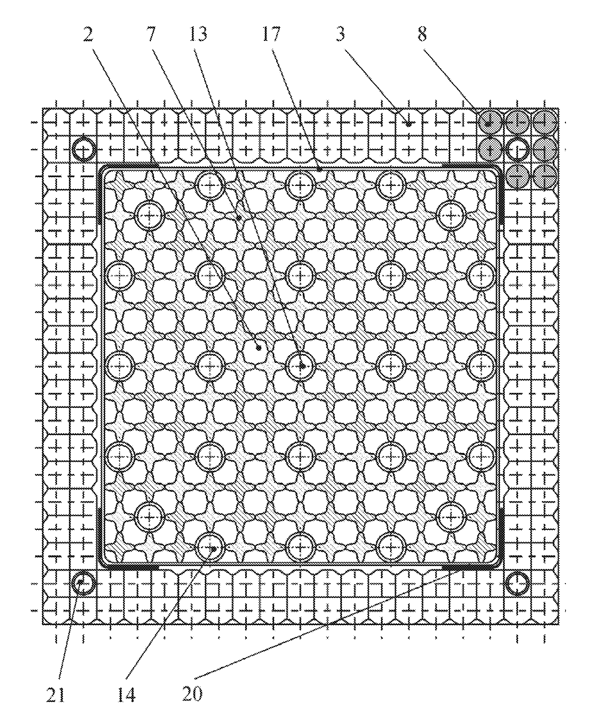
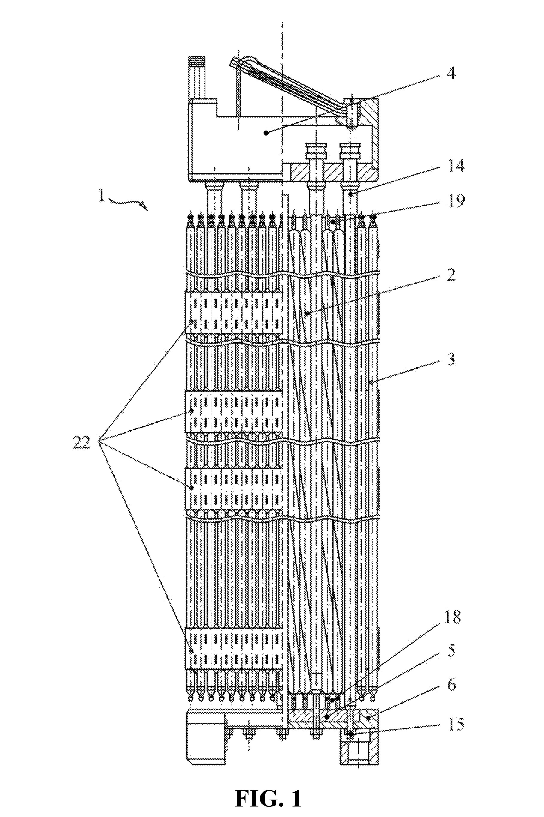
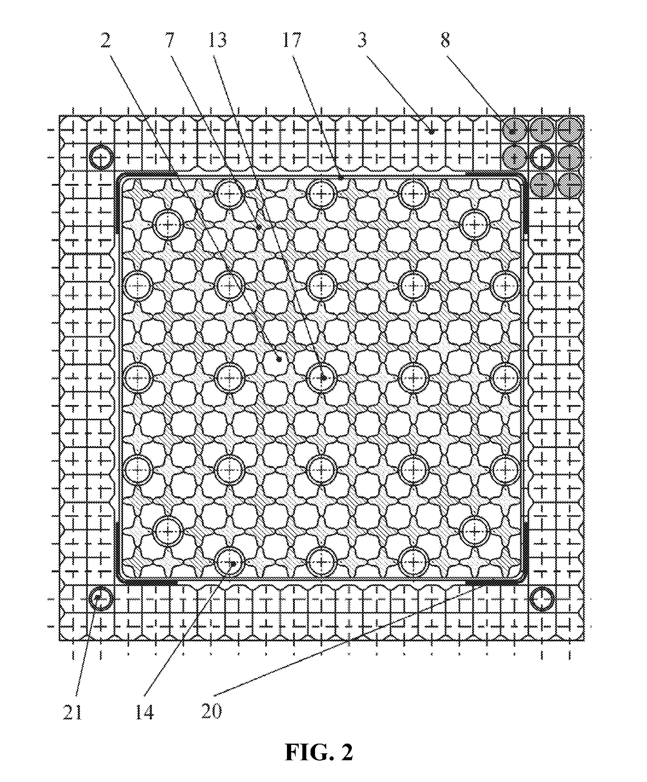
[0054]A fuel assembly designated as collective item 1 according to the invention is shown in FIG. 1. Fuel assembly 1 contains a seed region 2, a blanket region 3, a upper nozzle 4, a seed region lower nozzle 5, and a blanket region lower nozzle 6. As shown in FIG. 2, seed region 2 contains fuel element bundle 7, while blanket region 3 contains fuel element bundle 8. Each of the fuel elements in bundle 7 has a four-lobed profile that forms spiral spacer ribs, 9 (FIG. 6), along the length of a fuel element and contains a kernel, 10 (FIG. 7), that includes enriched uranium or plutonium, as well as a cladding made from a zirconium alloy, 11, that encircles it. A displacer, 12, is located inside kernel 10. All the fuel elements 7 make contact with each adjacent fuel element in bundle 7 at the spiral spacer rib 9 contact points. The spiral spacer rib 9 contact points stand away from one another in the axial direction by a distance equal 25% of the spiral line pitch value.

[0055]Each of the...

second embodiment

[0060]A fuel assembly designated as collective item 1′, according to the invention, is shown in FIG. 3. This assembly contains a seed region 2′, a blanket region 3′, a upper nozzle 4′, a seed region lower nozzle 5′, and a blanket region lower nozzle 6′. As shown in FIG. 4, seed region 2′ contains fuel elements' bundle 7′ while blanket region 3′ contains fuel elements' bundle 8′.

[0061]Similar to the fuel assembly that conforms to the first embodiment of the invention, each of fuel elements 7′ has a four-lobed profile that forms spiral spacer ribs 9 (FIG. 6) along the length of the fuel element and contains a kernel 10 (FIG. 7), which includes enriched uranium or plutonium, as well as a cladding 11, made from a zirconium alloy that surrounds the kernel. Displacer 12 is located inside of kernel 10. Each of fuel elements 8′ has a round shape in the plan view and is made from various ceramic formulations of thorium and uranium.

[0062]The fuel elements module 7′ and 8′ are arranged in the ...


PUM


Abstract

A 17×17 jacketless fuel assembly for a PWR-type light-water reactor uses thorium as the fuel. The fuel assembly has a square shape in the plan view, a seed region, a blanket region that encircles it, an upper nozzle, and a lower nozzle. The fuel elements of the seed region re arranged in the rows and columns of a square coordinate grid and have a four-lobed profile that forms spiral spacer ribs along the length of a fuel element. The blanket region contains a frame structure within which a bundle of fuel elements made from thorium with the addition of enriched uranium is positioned. The blanket region fuel elements are arranged in the two or three rows and columns of a square coordinate grid.

Description

PERTINENT ART[0001]The invention in general falls into the category of the structural elements of light-water nuclear reactors in which thorium is used as the fuel, and in particular, into the category of the structural elements of the jacketless fuel assemblies in the shape of a square from which the cores of water-cooled, water-moderated power reactors are formed, which are known as reactors of the PWR type (for example, the AP-1000, the EPR, etc.).PRIOR KNOWLEDGE[0002]Nuclear power is still an essential energy resource around the world today. Many countries that do not have adequate fossil fuel resources primarily rely on nuclear power to generate electricity. In many other countries, nuclear power is used as a competing source for the generation of electricity, which also increases the diversity of the types of energy used. In addition, nuclear power also makes a very significant contribution to the achievement of goals such as the management of the environmental pollution assoc...

Claims


Application Information

Patent Timeline
Patent Type & Authority Applications(United States)
IPC IPC(8): G21C3/34
CPCG21C1/024G21C3/02G21C3/326G21C3/3305Y02E30/38G21C5/20G21C2003/3265Y02E30/32G21C3/60G21C3/3265Y02E30/30
Inventor BASHKIRTSEV, SERGEY MIKHAILOVICHKUZNETSOV, VALENTIN FEDOROVICHKEVROLEV, VALERY VLADIMIROVICHMOROZOV, ALEXEY GLEBOVICH
Owner THORIUM POWER
Why Eureka
Try Eureka