Shim plate for tools for cutting machining as well as a tool

a technology of shim plate and tool, which is applied in the field of shim plate, can solve the problems of reducing and reducing the risk of serious damage to the basic body, so as to maintain the basic body, increase the service life of the cutting tool, and improve the strength of the basic body

Inactive Publication Date: 2011-12-22
SANDVIK INTELLECTUAL PROPERTY AB
View PDF15 Cites 8 Cited by
  • Summary
  • Abstract
  • Description
  • Claims
  • Application Information

AI Technical Summary

Benefits of technology

An advantage of the shim plate and the cutting tool according to the invention is that the use of a shim plate is made possible also in small cutting tools, for example in shank-end mills, or in cutting tools having a large number of insert seats without the strength of the basic body being affected appreciably. Thereby, the service life of the cutting tool increases by the combined effect of the maintained strength of the basic body, decreased wear of the basic body thanks to the shim plate, and the decreased risk of serious damage to the basic body upon possible insert breakdowns.
According to a preferred embodiment, the angle α is 5-30°, more preferably 10-25°. The advantage of this embodiment is that the difference in the thickness between the inner and outer parts of the shim plate then will be sufficiently great in order for the strength of the basic body to be maintainable at the same time as the shim plate provides a protecting effect at the envelope surface. Simultaneously, the ability of the shim plate to be held in place during machining is not compromised.
According to another embodiment, the bottom surface of the shim plate and the adjacent seat surface of the basic body include coupling means, for example in the form of serration surfaces or other connecting surfaces including male members intended to engage female members. The advantage of this embodiment is that the shim plate is fixed in its position in relation to the basic body and prevented from changing position in relation to the same.
According to an additional embodiment, the shim plate is wedge-shaped also in the axial direction, preferably in such a way that the thickness of the shim plate increases toward the front end surface. The advantage of this embodiment is that, for milling tools having a positive axial rake angle, it is possible to avoid deepening the insert seat appreciably farthest from the front end surface, and in such a way increase the strength of the basic body further.
According to yet another embodiment, the shim plate is manufactured from cemented carbide, which has the advantage that the shim plate upon a possible insert breakdown can be used as a cutting edge in the period of time it takes to interrupt the machining.

Problems solved by technology

In addition, the shim plate decreases the risk of serious damage to the basic body upon a possible insert breakdown.
Without a shim plate, there is risk of the basic body getting stuck in the workpiece leading to damage to the basic body, the spindle that drives the cutting tool, as well as to other co-operating parts in the machine tool in which the cutting tool is included.
A disadvantage of shim plates is that they decrease the strength of the basic body, since the insert seat has to be made deeper to make room for the shim plate for the size of the chip pockets not to be affected.
Since the size of the chip pockets is optimized in respect of chip release, it is not desirable to decrease the same.
In milling, the force is however primarily directed so that a deepening of the insert seat to make room for a shim plate significantly affects the strength.
For small cutting tools, such as shank-end mills, and for tools having many cutting inserts mounted, this becomes particularly problematic since the chip pockets proportionally already occupy a great part of the basic body.
The strength of the basic body is considerably impaired by a further deepening of the insert seats and the risk will be too great that cracks, as a consequence of overloading, should arise in the basic body upon machining.

Method used


Image

  • Shim plate for tools for cutting machining as well as a tool
  • Shim plate for tools for cutting machining as well as a tool
  • Shim plate for tools for cutting machining as well as a tool

Examples


first embodiment

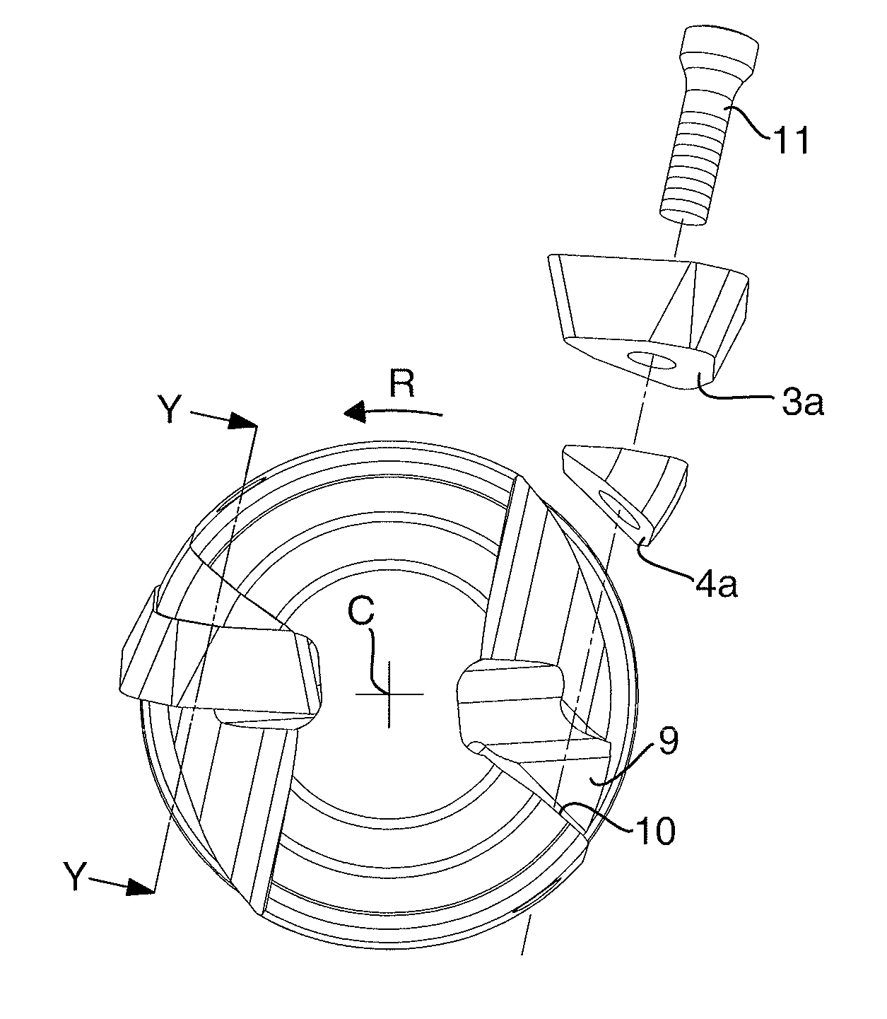
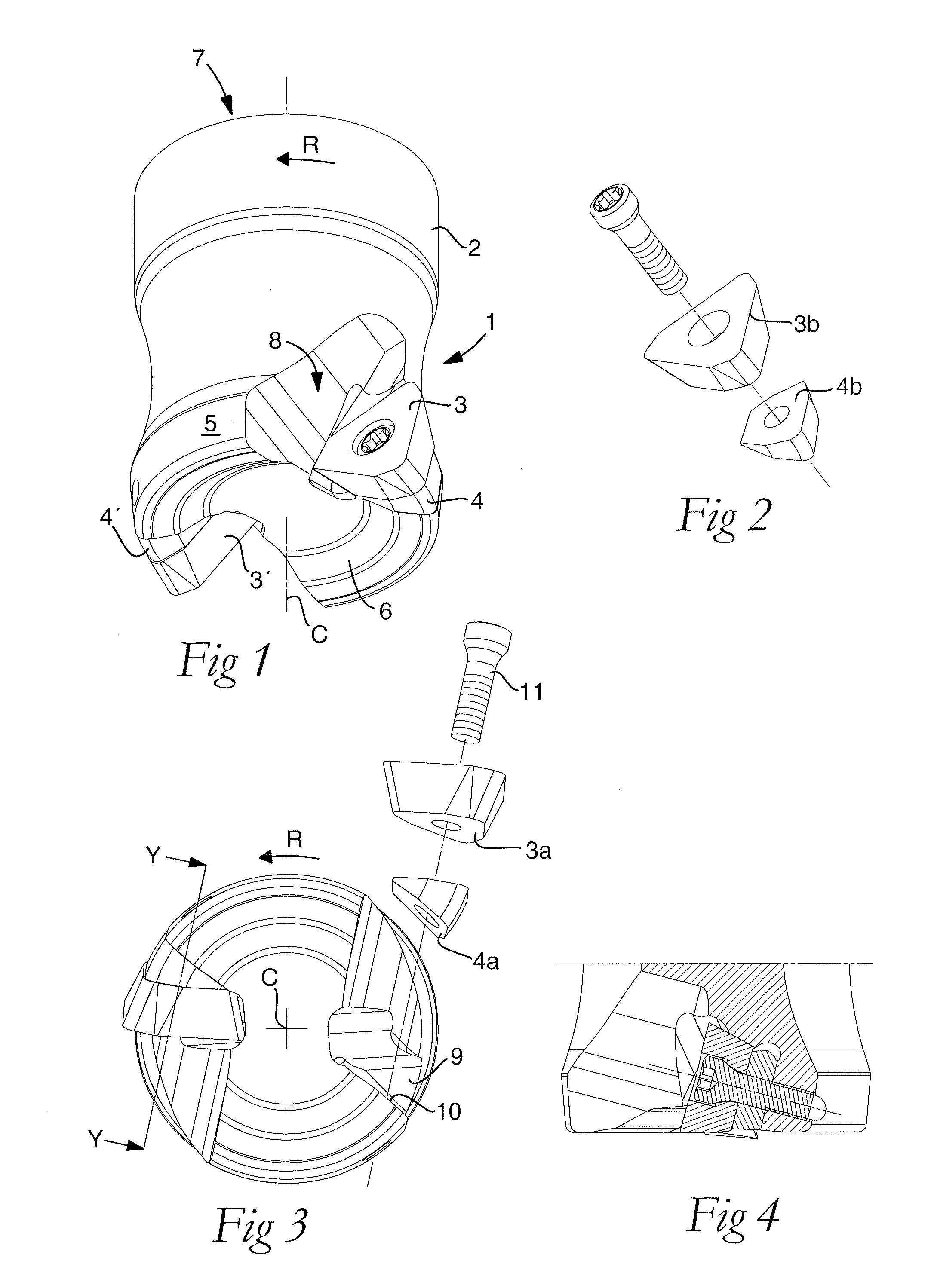
In FIGS. 1-9, the invention is shown. FIG. 1 shows an assembled cutting tool (1). The cutting tool includes a basic body (2) and one or more cutting inserts (3) each one of which co-operates with a shim plate (4). The basic body is rotatable in the direction of rotation R around a center axis C, hereinafter called the rotational axis of the basic body or only the rotational axis. The basic body has also a peripheral envelope surface (5) that is concentric with the rotational axis and that often but not necessarily is rotationally symmetric, and a front (6) and a rear end surface (7). Further, the basic body includes a number of chip pockets (8), which form indentations in the envelope surface as well as in the front end surface. In the chip pockets, insert seats (9) are arranged. Each insert seat includes a seat surface (10) to which a shim plate and a cutting insert can be mounted. Each cutting insert includes, among other things, a bottom surface (3a) and a main cutting edge (3b)....

third embodiment

Neither does the contact surface (4b) of the shim plate facing the bottom surface (3a) of the cutting insert need to be plane, but may, for example, include coupling means for the cutting insert (3) to be fixed better in relation to the shim plate (4). According to the invention, the contact surface of the shim plate facing the cutting insert has coupling means, which also in this case may be a serration surface or another connecting surface according to the above, where the bottom surface of the cutting insert adjacent to the shim plate co-operates with the contact surface of the shim plate. The bottom surface of the cutting insert is then provided with the corresponding coupling means.

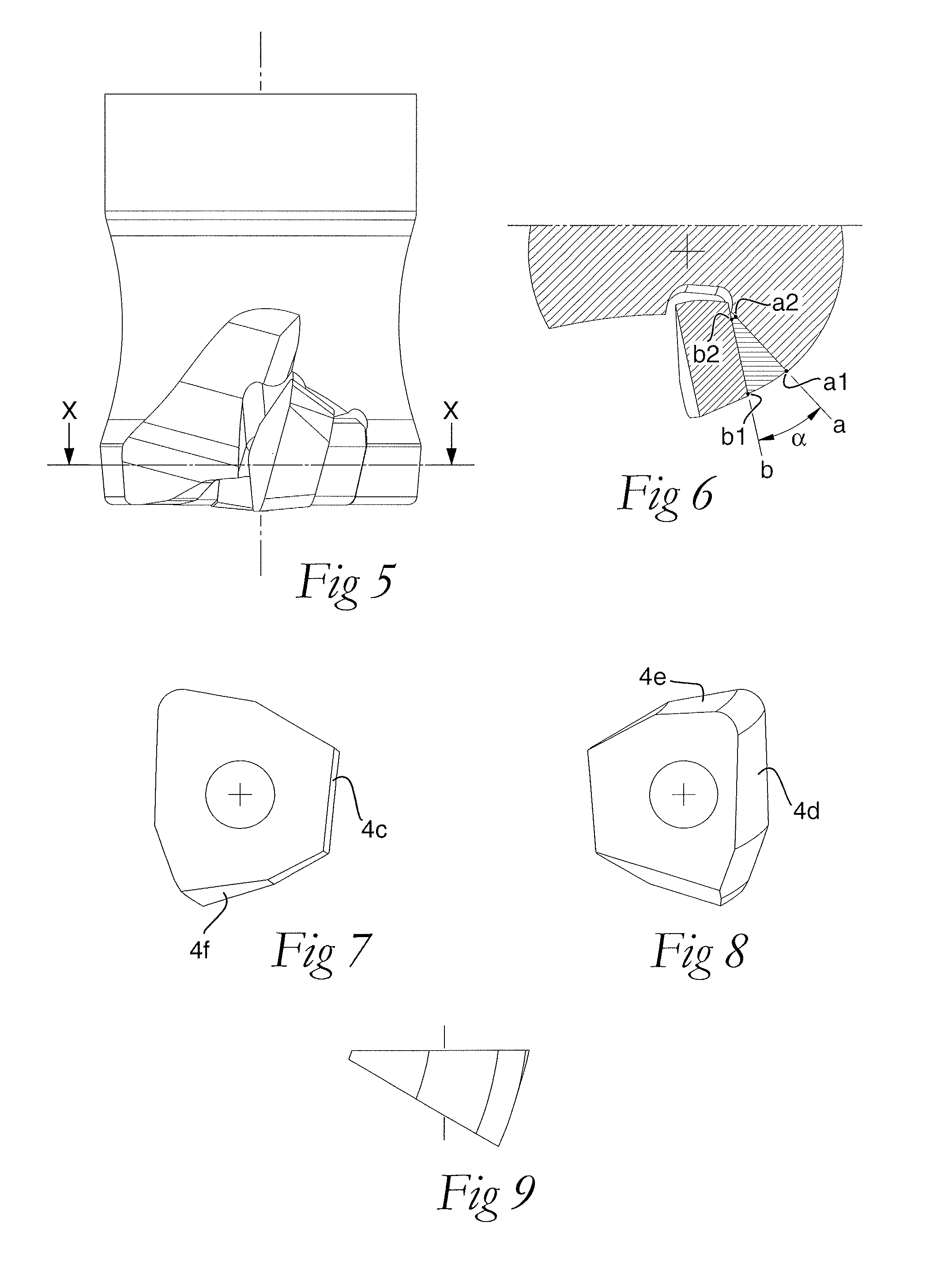
According to an additional embodiment of the invention, schematically shown in FIG. 11, the shim plate (4) is wedge-shaped also in the axial direction, preferably in such a way that the thickness of the shim plate increases toward the front end surface (6). In this embodiment, an arbitrary cross-sect...


PUM

PropertyMeasurementUnit
angleaaaaaaaaaa
angleaaaaaaaaaa
setting angleaaaaaaaaaa

Abstract

A shim plate for mounting in a cutting tool for rotary chip removing machining, the cutting tool including a basic body having a rotational axis, a peripheral envelope surface concentric with the rotational axis, a front end surface, and at least one insert seat including a seat surface, the basic body being rotatable in a direction of rotation and arranged to, in each insert seat against the seat surface, receive the shim plate and a mountable cutting insert adjacent to the shim plate. The shim plate includes a bottom surface adapted to adjoin to the seat surface of the basic body, a contact surface opposite to the bottom surface and adapted to adjoin to the cutting insert, and at least one side surface that extends between the bottom surface and the contact surface. In a radial cross-section orthogonal to the rotational axis and traversing the shim plate, an imaginary straight line (a) associated with the bottom surface, intersecting a point (a1) of the cross-section where the bottom surface is closest to the envelope surface of the basic body and a point (a2) of the cross-section where the bottom surface is closest to the rotational axis of the basic body, and an imaginary straight line (b) associated with the contact surface, intersecting a point (b1) of the cross-section where the contact surface is closest to the envelope surface of the basic body and a point (b2) of the cross-section where the contact surface is closest to the rotational axis of the basic body, diverge toward the envelope surface of the basic body and form an angle α with each other.

Description

This application claims priority under 35 U.S.C. §119 to Swedish Patent Application No. 1050661-6, filed on Jun. 22, 2010, which is incorporated by reference herein in its entirety.FIELD OF THE INVENTIONThe present invention relates generally to a shim plate for the use in cutting tools having detachable cutting inserts intended for rotary chip removing machining of metal, such as milling tools and drilling tools. The shim plate is of the type that is placed between the bottom surface of the cutting insert and the basic body of the cutting tool in order to protect the basic body upon possible insert breakdowns. The invention also relates to a cutting tool for rotary chip removing machining, which includes one or more shim plates.BACKGROUND OF THE INVENTIONA cutting tool for rotary chip removing machining of workpieces includes a basic body and a number of cutting inserts, as well as in some cases shim plates mounted between the cutting insert and the basic body as a protection for t...

Claims


Application Information

Patent Timeline
Patent Type & Authority Applications(United States)
IPC IPC(8): B23C5/22B23C9/00
CPCY10T407/192B23C2210/166B23C5/2208Y10T407/1932Y10T407/1928Y10T407/28Y10T407/1916B23C5/22B23C5/20B23B51/08B23B27/22B23B51/00B23C5/00B23C9/00
Inventor PANTZAR, GORAN
Owner SANDVIK INTELLECTUAL PROPERTY AB
Why Eureka
Try Eureka