Microfluidic device with pwm controlled PCR heater

Inactive Publication Date: 2011-12-22
GENEASYS
View PDF11 Cites 2 Cited by
  • Summary
  • Abstract
  • Description
  • Claims
  • Application Information

AI Technical Summary

Benefits of technology

[0090]The easily usable, mass-producible, and inexpensive microfluidic device accepts a sample containing nucleic acids and then utilizing the device's PCR chamber amplifies the nucleic acid targets in the sample.
[0091]The PCR section is controlled by a

Problems solved by technology

Insufficient stringency can result in a high degree of nonspecific binding.
Excessive stringency can lead to a failure of appropriate binding, which results in diminished sensitivity.
Despite the advantages that molecular diagnostic tests offer, the growth of this type of testing in the clinical laboratory has been slower than expected and remains a minor part of the practice of laboratory medicine.
This is primarily due to the complexity and costs associated with nucleic acid testing compared with tests based

Method used


Image

  • Microfluidic device with pwm controlled PCR heater
  • Microfluidic device with pwm controlled PCR heater
  • Microfluidic device with pwm controlled PCR heater

Examples


Embodiment Construction

Overview

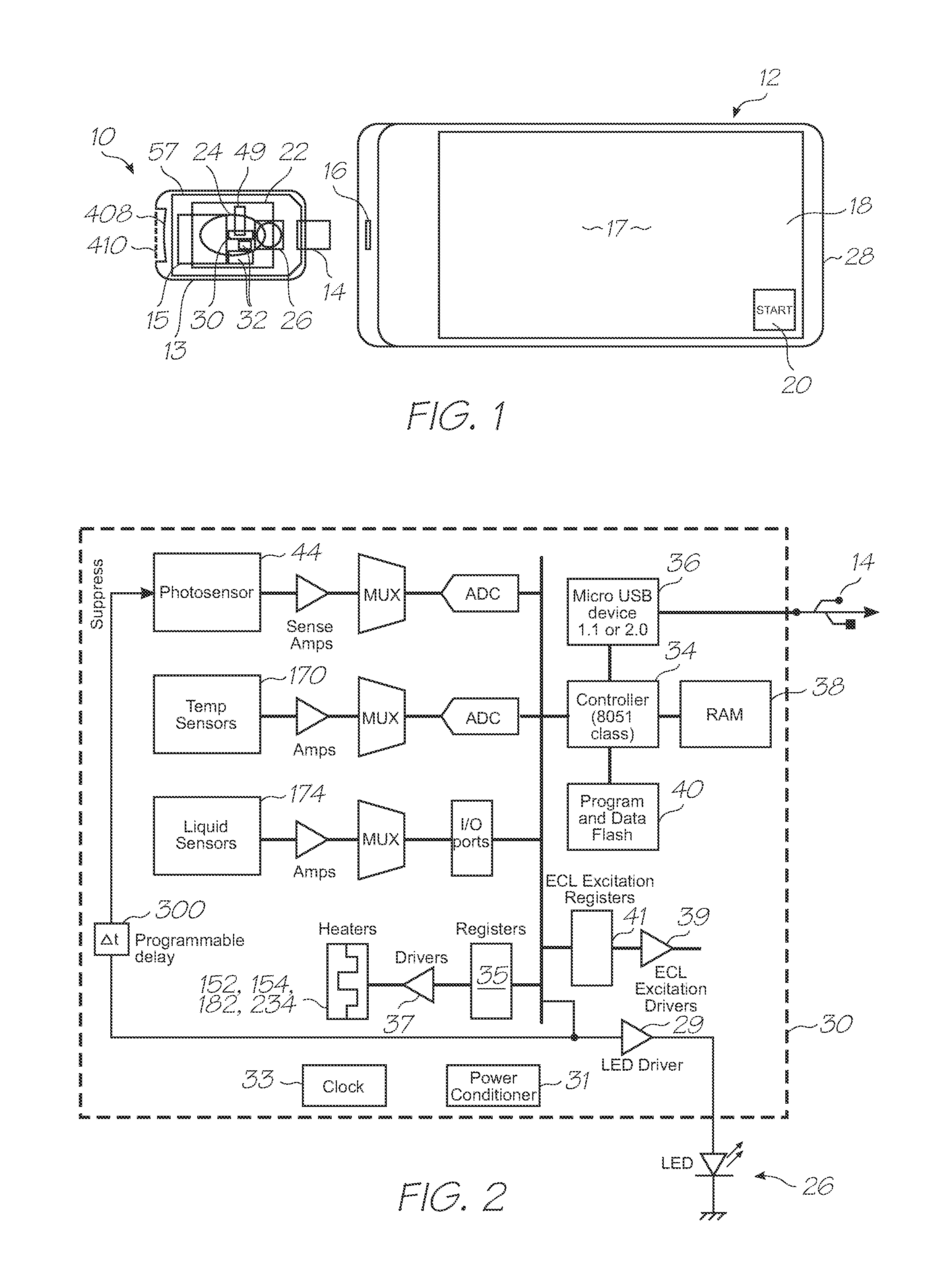
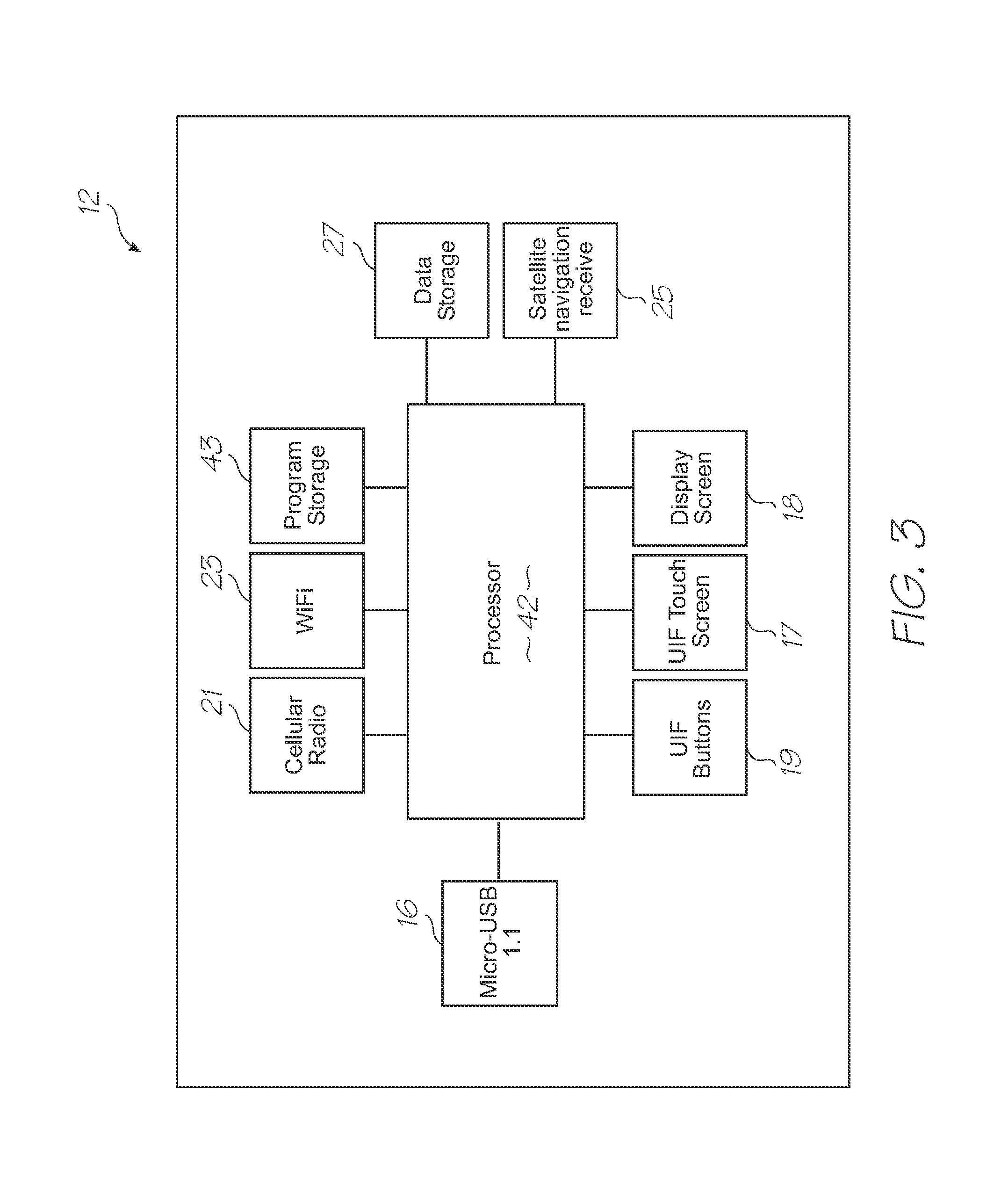
[0192]This overview identifies the main components of a molecular diagnostic system that incorporates embodiments of the present invention. Comprehensive details of the system architecture and operation are set out later in the specification.

[0193]Referring to FIGS. 1, 2, 3, 96 and 97, the system has the following top level components:

[0194]Test modules 10 and 11 are the size of a typical USB memory key and very cheap to produce. Test modules 10 and 11 each contain a microfluidic device, typically in the form of a lab-on-a-chip (LOC) device 30 preloaded with reagents and typically more than 1000 probes for the molecular diagnostic assay (see FIGS. 1 and 96). Test module 10 schematically shown in FIG. 1 uses a fluorescence-based detection technique to identify target molecules, while test module 11 in FIG. 96 uses an electrochemiluminescence-based detection technique. The LOC device 30 has an integrated photosensor 44 for fluorescence or electrochemiluminescence detection (de...


PUM

PropertyMeasurementUnit
Timeaaaaaaaaaa
Timeaaaaaaaaaa
Timeaaaaaaaaaa

Abstract

A microfluidic device having a supporting substrate, a sample inlet for receiving a sample of biological material having nucleic acid sequences, a microsystems technology (MST) layer having a polymerase chain reaction (PCR) section for amplifying the nucleic acid sequences, the PCR section having at least one heater for thermally cycling the nucleic acid sequences through a denaturing phase, an annealing phase and a primer extension phase, and, CMOS circuitry between the MST layer and the supporting substrate, the CMOS circuitry configured to energize the at least one heater with a pulse width modulated (PWM) signal during the thermal cycling.

Description

FIELD OF THE INVENTION[0001]The present invention relates to diagnostic devices that use microsystems technologies (MST). In particular, the invention relates to microfluidic and biochemical processing and analysis for molecular diagnostics.CO-PENDING APPLICATIONS[0002]The following applications have been filed by the Applicant which relate to the present application:GBS001USGBS002USGBS003USGBS005USGBS006USGSR001USGSR002USGAS001USGAS002USGAS003USGAS004USGAS006USGAS007USGAS008USGAS009USGAS010USGAS012USGAS013USGAS014USGAS015USGAS016USGAS017USGAS018USGAS019USGAS020USGAS021USGAS022USGAS023USGAS024USGAS025USGAS026USGAS027USGAS028USGAS030USGAS031USGAS032USGAS033USGAS034USGAS035USGAS036USGAS037USGAS038USGAS039USGAS040USGAS041USGAS042USGAS043USGAS044USGAS045USGAS046USGAS047USGAS048USGAS049USGAS050USGAS054USGAS055USGAS056USGAS057USGAS058USGAS059USGAS060USGAS061USGAS062USGAS063USGAS065USGAS066USGAS067USGAS068USGAS069USGAS070USGAS080USGAS081USGAS082USGAS083USGAS084USGAS085USGAS086USGAS087USGAS...

Claims


Application Information

Patent Timeline
IPC IPC(8): C40B60/12C12M1/00
CPCB01L3/5027Y10T436/25B01L3/502738B01L7/52B01L2200/10B01L2300/023B01L2300/024B01L2300/0636B01L2300/0654B01L2300/0883B01L2300/10B01L2300/1827B01L2400/0406B01L2400/0633B01L2400/0677B01L2400/0688F16K99/003F16K99/0036G01N27/223C12Q1/68Y10T436/107497Y10T436/173845Y10T436/143333Y10T436/11Y10T436/145555Y10T436/203332Y10T436/25375B01L3/502707Y10T137/0352Y10T137/0391Y10T137/1044Y10T137/206Y10T137/2076Y10T137/2202Y02A90/10
Inventor FACER, GEOFFREY RICHARDSILVERBROOK, KIAAZIMI, MEHDI
Owner GENEASYS
Why Eureka
Try Eureka