Abnormality diagnosis system and method for diagnosing abnormality in filter regeneration system

a filter regeneration and abnormality diagnosis technology, applied in mechanical equipment, machines/engines, exhaust treatment, etc., can solve the problems of abnormal pm discharge amount from the engine, negative impact on the operation of the internal combustion engine, erosion or breakage of the filter, etc., and achieve the effect of higher accuracy

Inactive Publication Date: 2011-12-29
TOYOTA JIDOSHA KK
View PDF1 Cites 9 Cited by
  • Summary
  • Abstract
  • Description
  • Claims
  • Application Information

AI Technical Summary

Benefits of technology

[0073]According to the present invention, whether or not abnormality occurs in the filter regeneration system causing excessive execution frequency of the regeneration process can be diagnosed with higher accuracy.

Problems solved by technology

In this case, operation of the internal combustion engine may be negatively affected by increase of the back-pressure, if the PM accumulation amount at the filter should increase excessively.
Further, if the PM accumulates excessively at the filter and is oxidized, the filter temperature may increase excessively by the oxidation heat, which may eventually cause erosion or breakage of the filter.
Further, a number of consecutive regenerations, namely series of busy regeneration periods whose regeneration time intervals between the decisions for the regeneration process are shorter than a threshold value, is counted, and if the number exceeds a threshold value, the PM discharged amount from the engine is judged abnormal.

Method used


Image

  • Abnormality diagnosis system and method for diagnosing abnormality in filter regeneration system
  • Abnormality diagnosis system and method for diagnosing abnormality in filter regeneration system
  • Abnormality diagnosis system and method for diagnosing abnormality in filter regeneration system

Examples


embodiment 1

[0101](Outline Constitution of Internal Combustion Engine and Intake-Exhaust System Thereof)

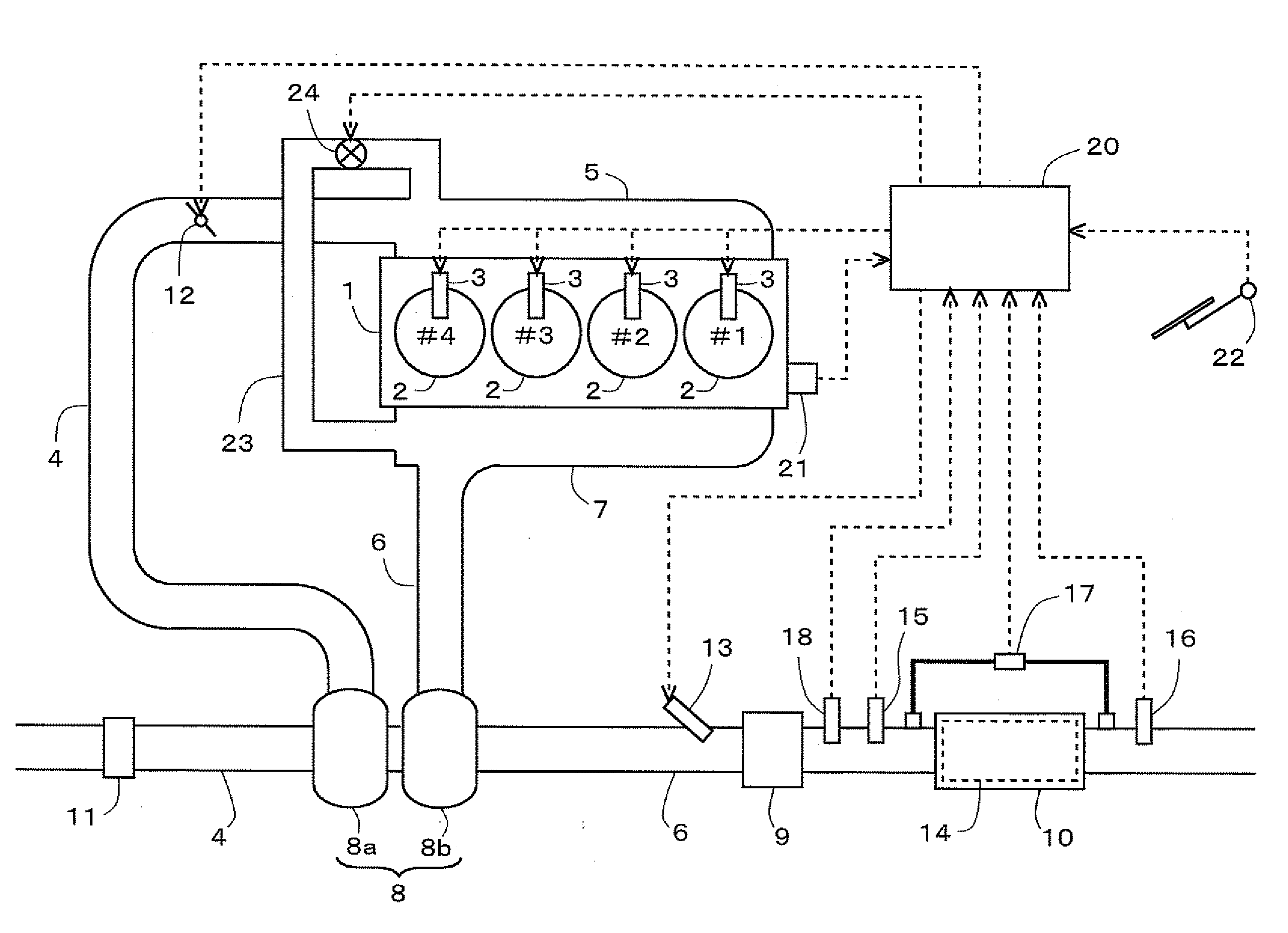
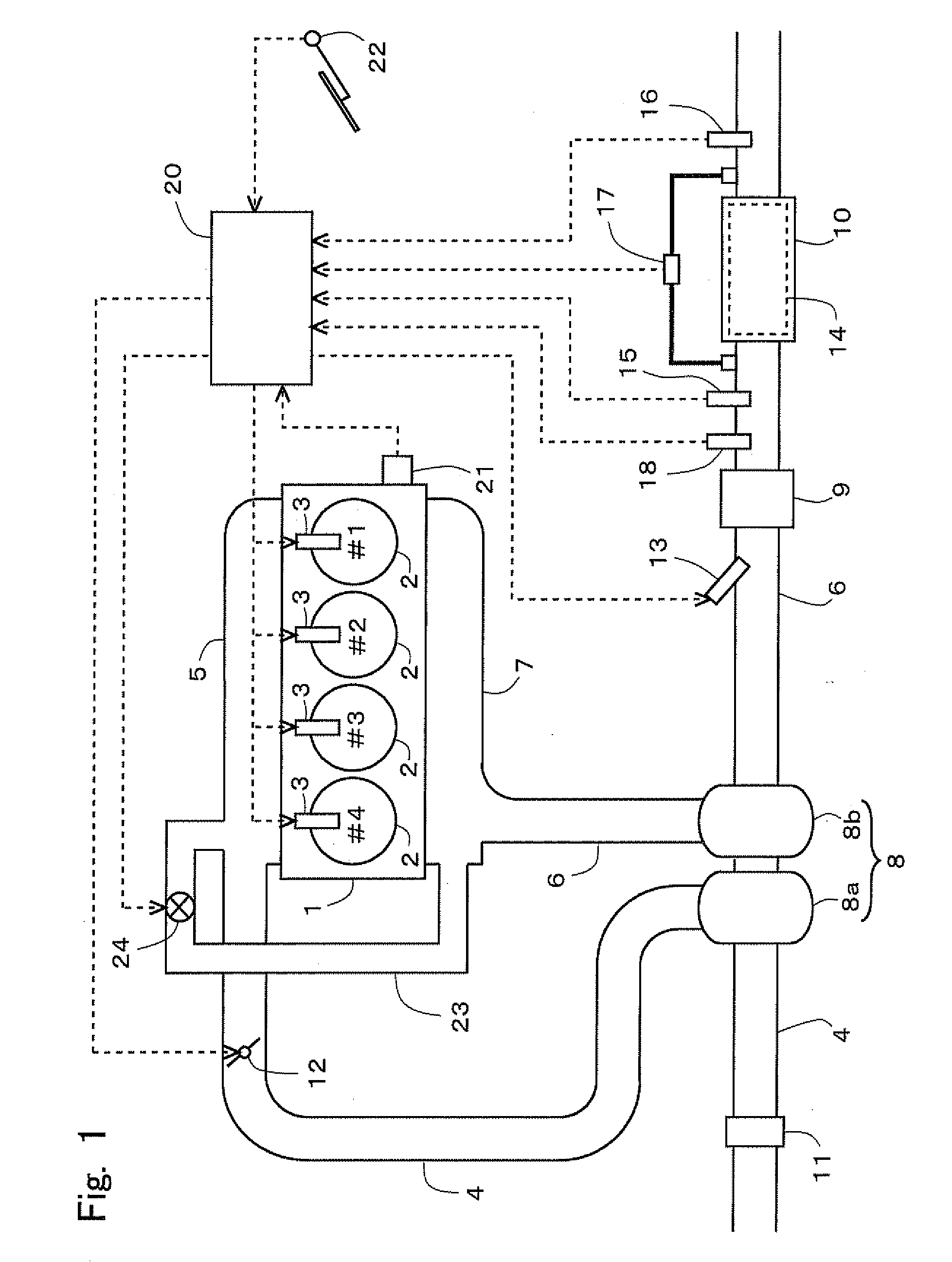
[0102]FIG. 1 is a schematic representation of an outline constitution of an internal combustion engine and an intake-exhaust system thereof pursuant to the present embodiment. The internal combustion engine 1 is a diesel engine for driving a vehicle and has 4 cylinders 2. Each cylinder 2 is provided with a fuel injection valve 3 for injecting a fuel directly into the cylinder 2.

[0103]The internal combustion engine 1 is connected with an intake manifold 5 and an exhaust manifold 7. The intake manifold 5 is connected with an end of the intake passage 4. The exhaust manifold 7 is connected with an end of the exhaust passage 6.

[0104]The intake passage 4 is provided with a compressor housing 8a of a turbocharger 8. The exhaust passage 6 is provided with a turbine housing 8b of the turbocharger 8. While, the intake manifold 5 and the exhaust manifold 7 are interconnected by an EGR passage 23. The E...

embodiment 2

[0155]An outline constitution of an internal combustion engine and an intake-exhaust system thereof pursuant to the present embodiment is similar to Embodiment 1.

[0156](Regeneration Process)

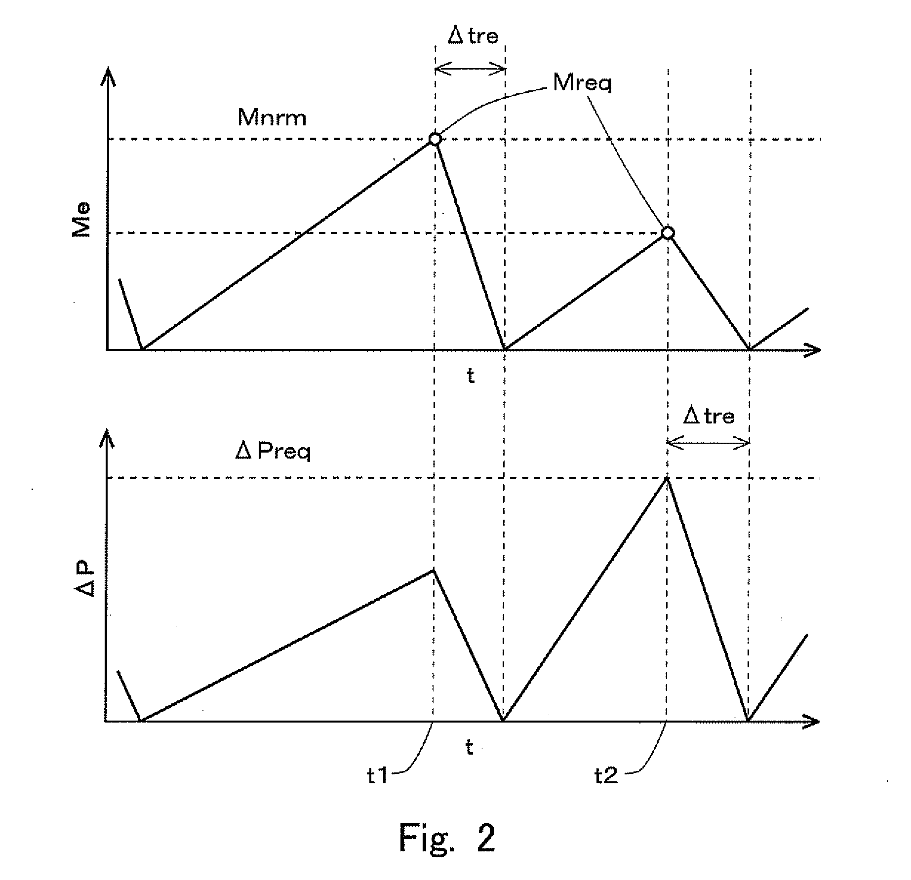
[0157]Pursuant to the present embodiment, as in Embodiment 1, the regeneration process is carried out by adding the fuel through the fuel addition valve 13. Now, the timings of initiation and termination of the execution of the regeneration process pursuant to the present embodiment will be described with reference to FIG. 9. FIG. 9 is graphs showing the time courses of the estimated PM accumulation amount Me and the differential pressure ΔP pursuant to the present embodiment.

[0158]The initiation timing of the execution of the regeneration process pursuant to the present embodiment is similar to Embodiment 1. Namely, the execution of the regeneration process is initiated, when the estimated PM accumulation amount Me reaches a pre-determined regeneration requiring accumulation amount Mnrm (t1 in F...

embodiment 3

[0184]The outline constitution of an internal combustion engine and an intake-exhaust system thereof pursuant to the present embodiment is similar to Embodiment 1. Further, the regeneration process pursuant to the present embodiment is executed according to a method similar to Embodiment 1.

[0185](Diagnosis of Abnormality in Filter Regeneration System)

[0186]Examples of the abnormality in the filter regeneration system causing excessive execution frequency of the regeneration process include the following (a) to (e):

[0187](a) an excessive PM discharge amount from an internal combustion engine 1;

[0188](b) decrease in the continuous regeneration ability of a NOx storage reduction catalyst 14;

[0189](c) disorder in the regeneration process;

[0190](d) increase of the accumulation amount of materials poorly removable by the regeneration process (e.g. ashes); and

[0191](e) failure of a differential pressure sensor 17 (faulty offset or faulty sensitivity).

[0192]The (a) above is caused by poor s...


PUM


Abstract

The invention intends to provide a technology which makes it possible to diagnose with higher accuracy whether or not abnormality occurs in a filter regeneration system causing excessive execution frequency of a regeneration process. The filter regeneration system initiates execution of the regeneration process, incase an estimated particulate matter (PM) accumulation amount at the filter reaches a pre-determined regeneration requiring accumulation amount; or in case the pressure upstream of the filter or the differential pressure across the filter reaches a pre-determined regeneration requiring value, the value being larger than the pressure or the differential pressure corresponding to the regeneration requiring accumulation amount. Then, the diagnosis is carried out based on a ratio of an estimated PM accumulation amount at the initiation of the execution of the regeneration process to the regeneration requiring accumulation amount.

Description

TECHNICAL FIELD[0001]The present invention relates to a system and a method for diagnosing abnormality in a system executing a regeneration process for a particulate filter placed in an exhaust passage of an internal combustion engine.BACKGROUND ART[0002]A particulate filter (hereinafter simply referred to as a “filter”) may be placed in an exhaust passage of an internal combustion engine to trap particulate matter (hereinafter referred to as “PM”) in the exhaust gas of the internal combustion engine. In this case, operation of the internal combustion engine may be negatively affected by increase of the back-pressure, if the PM accumulation amount at the filter should increase excessively. Further, if the PM accumulates excessively at the filter and is oxidized, the filter temperature may increase excessively by the oxidation heat, which may eventually cause erosion or breakage of the filter. To prevent such problems, a filter regeneration system conducting a regeneration process by...

Claims


Application Information

Patent Timeline
Patent Type & Authority Applications(United States)
IPC IPC(8): F01N11/00
CPCF01N3/025F01N11/002Y02T10/47F01N2900/0601F01N2900/1606F01N2550/04F01N9/002Y02T10/40
Inventor SHIBATA, DAISUKEKITAURA, KOICHISAWADA, HIROSHITSUJI, TATSUYA
Owner TOYOTA JIDOSHA KK
Why Eureka
Try Eureka