Cyclic Impact-Sliding Fatigue Wear Testing Instrument

a fatigue wear and fatigue technology, applied in the direction of instruments, abrasion/wear resistance investigation, repeated/pulsating force-based materials, etc., can solve the problems of difficult coating properties evaluation, tool wear prevention becomes an important issue, and die wear can be a problem

Active Publication Date: 2011-12-29
NIE YINING +1
View PDF0 Cites 22 Cited by
  • Summary
  • Abstract
  • Description
  • Claims
  • Application Information

AI Technical Summary

Problems solved by technology

Due to the increasing use of advanced materials, tool wear prevention has become an important issue in the manufacturing and machining of those materials.
For instance, die wear can be a problem during the stamping of advanced high strength steels (AHSS) for production of automotive parts.
Because the PVD and CVD coatings are usually a thin ceramic layer deposited on the tool steels and cements (e.g., WC-Co), evaluation of the coating properties becomes very challenging.
Peeling, chipping, circular cracking and fatigue cracking can be the coating failure mechanisms under ultra-high contact stresses during the metal-forming.
However, currently available laboratory tests on the hard coatings use operating conditions that do not correspond to actual stress situations and levels of stamping die production, thus the lab tests cannot replicate the coating failure phenomena.
There is no laboratory testing method or instrument that can be effectively used to produce a combination of an impact motion and a sliding motion in each testing cycle with maximum contact pressures similar to actual contact stresses applied to dies, tools and coatings in metal-manufacturing production.
Biomedical implants such as hip and knee replacement with and without PVD / CVD coatings also suffer from impact-sliding wear failures caused by impact and sliding forces.

Method used


Image

  • Cyclic Impact-Sliding Fatigue Wear Testing Instrument
  • Cyclic Impact-Sliding Fatigue Wear Testing Instrument
  • Cyclic Impact-Sliding Fatigue Wear Testing Instrument

Examples


example 1

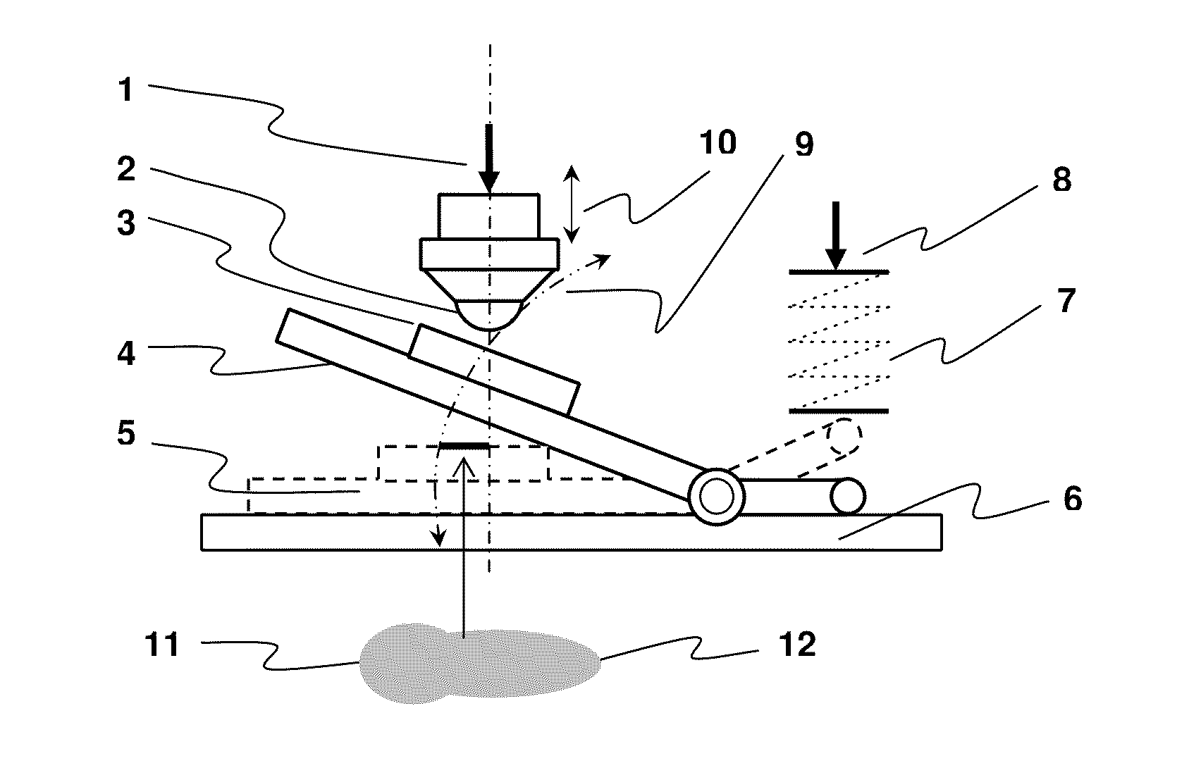
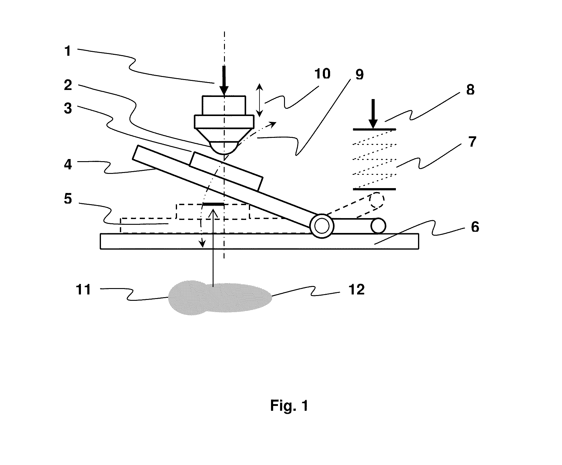
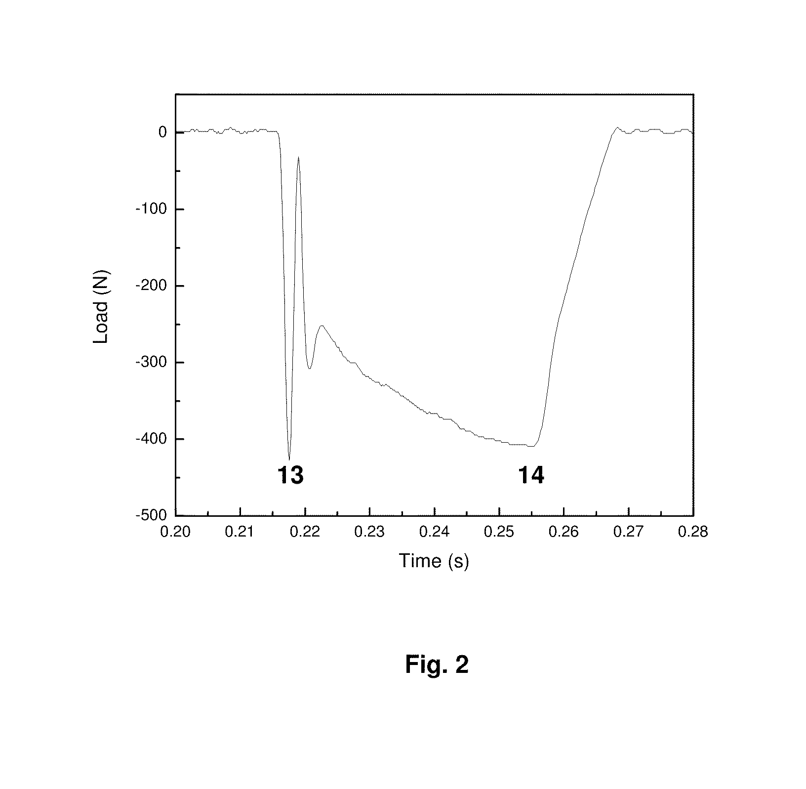
[0028]A load curve includes two parts, an impact force 13 and a build-up pressing force 14, in each cycle, as shown in FIG. 2. The impact force is adjusted to be in a range of 0 to 3000 Newtons (N). The pressing force is adjusted to be in a range of 10 N to 1500 N. When the gap between the impact ball and the tested sample is 0, the impact force is 0 N, which means that the test is operating only in the sliding mode. Different combinations of an impact force and a pressing force are obtained by varying the gap distance d and the driving force Fd provided by the driving device. For the case that the driving device is an air cylinder, different driving forces are obtained by regulating its air pressure. FIG. 2 is an example of a load curve of one cycle where the combination of a 400 N impact force and a 400 N pressing force at a frequency of 10 Hz is presented. After a short period of impacting under a 400 N load, a quasi-static pressing load 400 N is built up and is finally equal to ...

example 2

[0029]The sample 3 holder on the rocker 4 in FIG. 1 is added with a heating element. For instance, a heating tube is embedded into the sample holder and rocker so that the tested sample can be heated up to 600° C. Thus, temperature and annealing effects can be studied.

example 3

[0030]An ultrasonic sensor and piezoelectric transducer are added onto the sample 3 holder and the shaft of the driving device 1. The sensor and transducer are used to detect the signals of the sample failure. When the peeling, chipping and fatigue cracking occur, ultrasonic sounds will be generated. By capturing the ultrasonic signals, the number of the testing cycles before failure can be determined.


PUM

PropertyMeasurementUnit
frequencyaaaaaaaaaa
reciprocating sliding frequencyaaaaaaaaaa
frequencyaaaaaaaaaa

Abstract

This invention deals with a testing instrument that is used to investigate failure behavior of items subject to impact and sliding forces. The testing instrument produces an impact motion and a sliding motion in each testing cycle with maximum contact pressure similar to actual stresses applied to the items during real applications. The invented instrument simulates wear conditions and failure behaviors of biomedical implants, components, tools and coatings which are observed in practical applications.

Description

CROSS-REFERENCE TO RELATED APPLICATIONS[0001]Not applicable.STATEMENT REGARDING FEDERALLY SPONSORED RESEARCH OR DEVELOPMENT[0002]Not applicable.REFERENCE TO SEQUENCE LISTING, A TABLE, OR A COMPUTER PROGRAM LISTING COMPACT DISC APPENDIX[0003]Not applicable.DESCRIPTIONBackground of the Invention[0004]Due to the increasing use of advanced materials, tool wear prevention has become an important issue in the manufacturing and machining of those materials. For instance, die wear can be a problem during the stamping of advanced high strength steels (AHSS) for production of automotive parts. New die materials, surface treatment and coatings technology have to be developed to solve wear problems. The die materials include H13, P20, S7, D2, M2 and other tool steels. Surface treatment includes quench hardening, flame hardening, laser hardening, induction hardening, nitriding, carburizing and nitrocarburizing. The surface coatings include electroplated or electroless coatings, plasma and therma...

Claims


Application Information

Patent Timeline
Patent Type & Authority Applications(United States)
IPC IPC(8): G01N3/00
CPCG01N3/56G01N2203/0007G01N2203/0016G01N3/34G01N2203/001
Inventor NIE, YININGZHANG, JINGZENG
Owner NIE YINING
Why Eureka
Try Eureka