
Sheet cutter and belt processing tool

Inactive Publication Date: 2011-12-29
NITTA CORP
View PDF5 Cites 9 Cited by
  • Summary
  • Abstract
  • Description
  • Claims
  • Application Information

AI Technical Summary

Benefits of technology

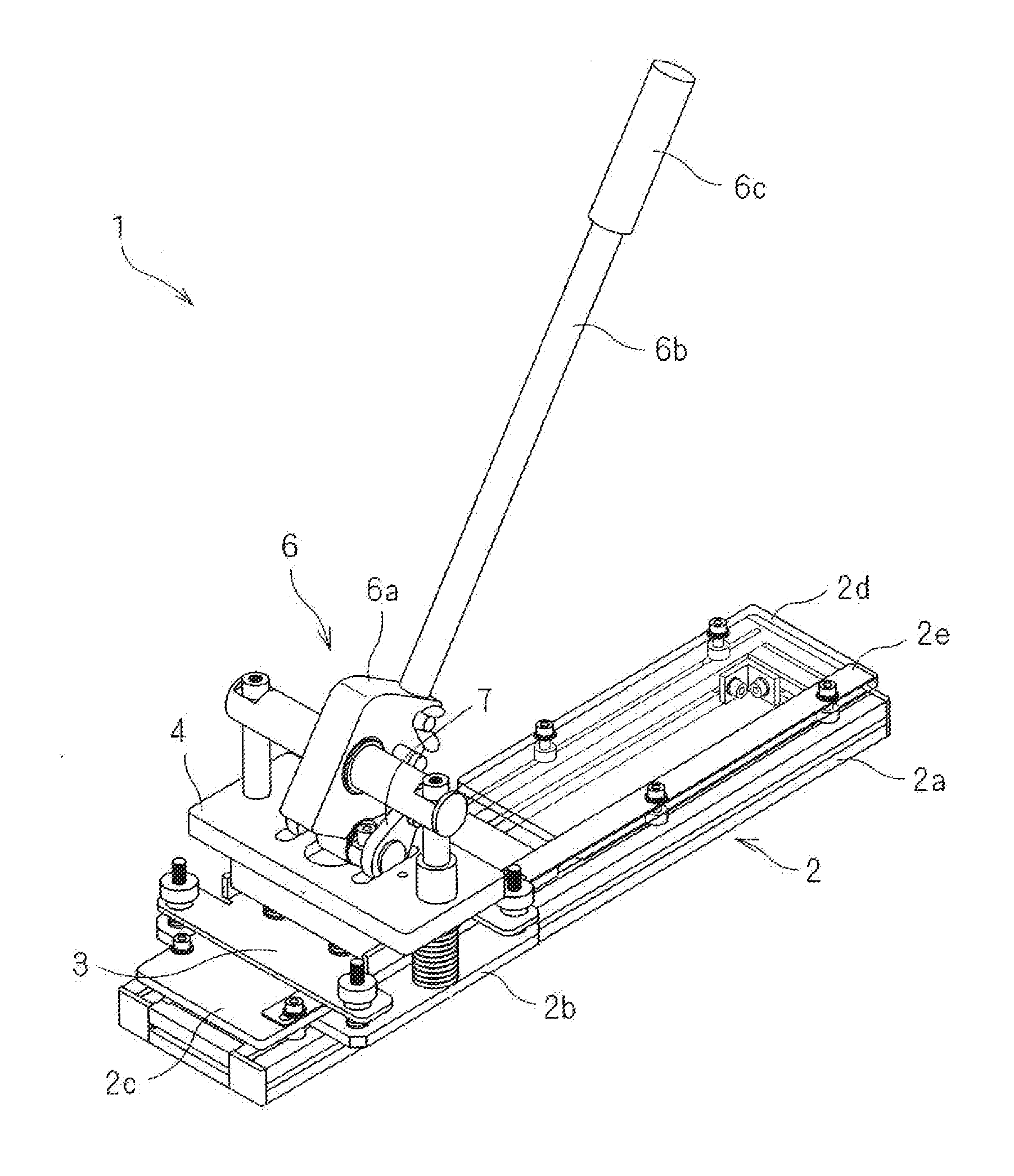
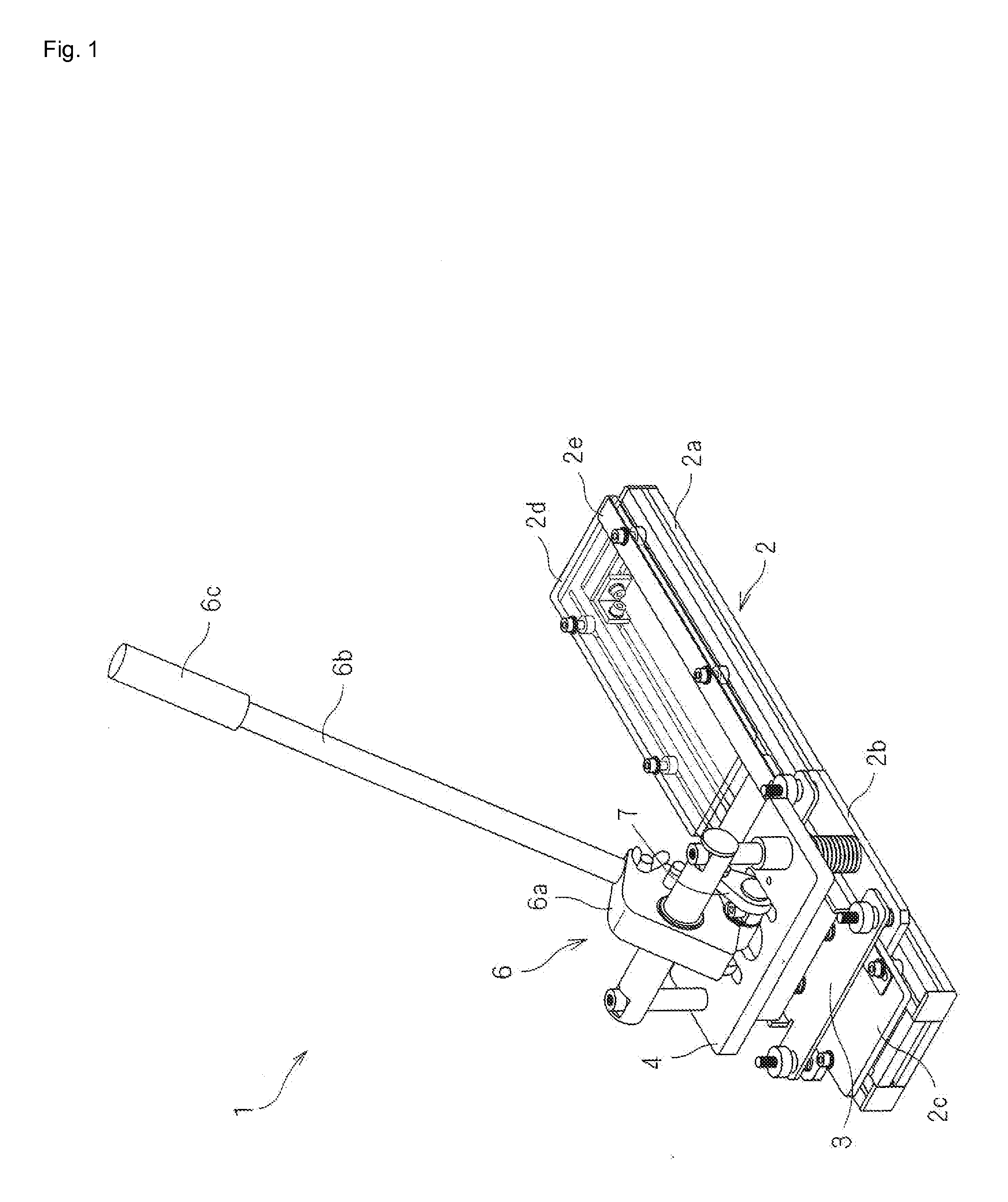
[0012]According to the sheet cutter, when the die holding plate including the blade of the Thomson die (hereinafter referred to as Thomson blade) is lowered by the lever operation and the planar cam, the die holding plate presses downwardly the stripper plate during descent. Therefore, the sheet is held between the stripper plate and the mounting table, and above there, the Thomson blade protrudes from the slit of the stripper plate, thereby cutting the sheet. Thus, a single operation of rotating the lever ensures the smooth sequence of “pressing the sheet” and “cutting the sheet.”
[0013]Also, the operation force is increased by the lever, making it possible to apply a large force to depress the die holding plate. The planar cam is used at the point of action contacted with the die holding plate, making it possible to apply a larger cutting force.
[0014]Furthermore, when the lever is rotated to the original position, the Thomson blade is pulled up by the means for pulling up the die holding plate. At that occasion, the stripper plate is locked at a predetermined height position from the upper surface of the mounting table. Therefore, the sheet attached to the Thomson blade is obstructed and released by the stripper plate. Consequently, “the release of the sheet” can be easily and safely carried out by the operation of returning the lever to the original position.
[0015]The belt processing tool has a similar construction to that of the sheet cutter, and the Thomson die includes the blade having a predetermined shape for joining together the end portions of the belt. Therefore, the end portions of the belt can be cut into a complicated joint shape, such as the saw-tooth shape.

Problems solved by technology

It is difficult to form the shape of the saw-tooth shape by cutting the belt with the scissors into mountains one by one, as in the case of the conventional technique.
It is time consuming to form into the saw-tooth shape by blanking with the Thomson blade into mountains one by one.
The finishing accuracy thereof is unstable.
However, the finishing accuracy thereof is unstable.
Even in that case, there occurs the disadvantage that the mountain-shaped front end portions of the belt bite into the blade, failing to depart from the blade.
It is a complicated work to release the front end portions every time.
It is also dangerous to work with the force applied by fingers at a location close to the blade.Patent document 1: Japanese Unexamined Patent Publication No. 2003-205554Patent document 2: Japanese Unexamined Patent Publication No. 2001-162590

Method used


Image

  • Sheet cutter and belt processing tool
  • Sheet cutter and belt processing tool
  • Sheet cutter and belt processing tool

Examples


Embodiment Construction

[0023]The belt processing tool according to an embodiment of the present invention is described below with reference to the drawings. The sheet cutter of the present invention is substantially the same as the belt processing tool, except that a cutting object thereof is a sheet.

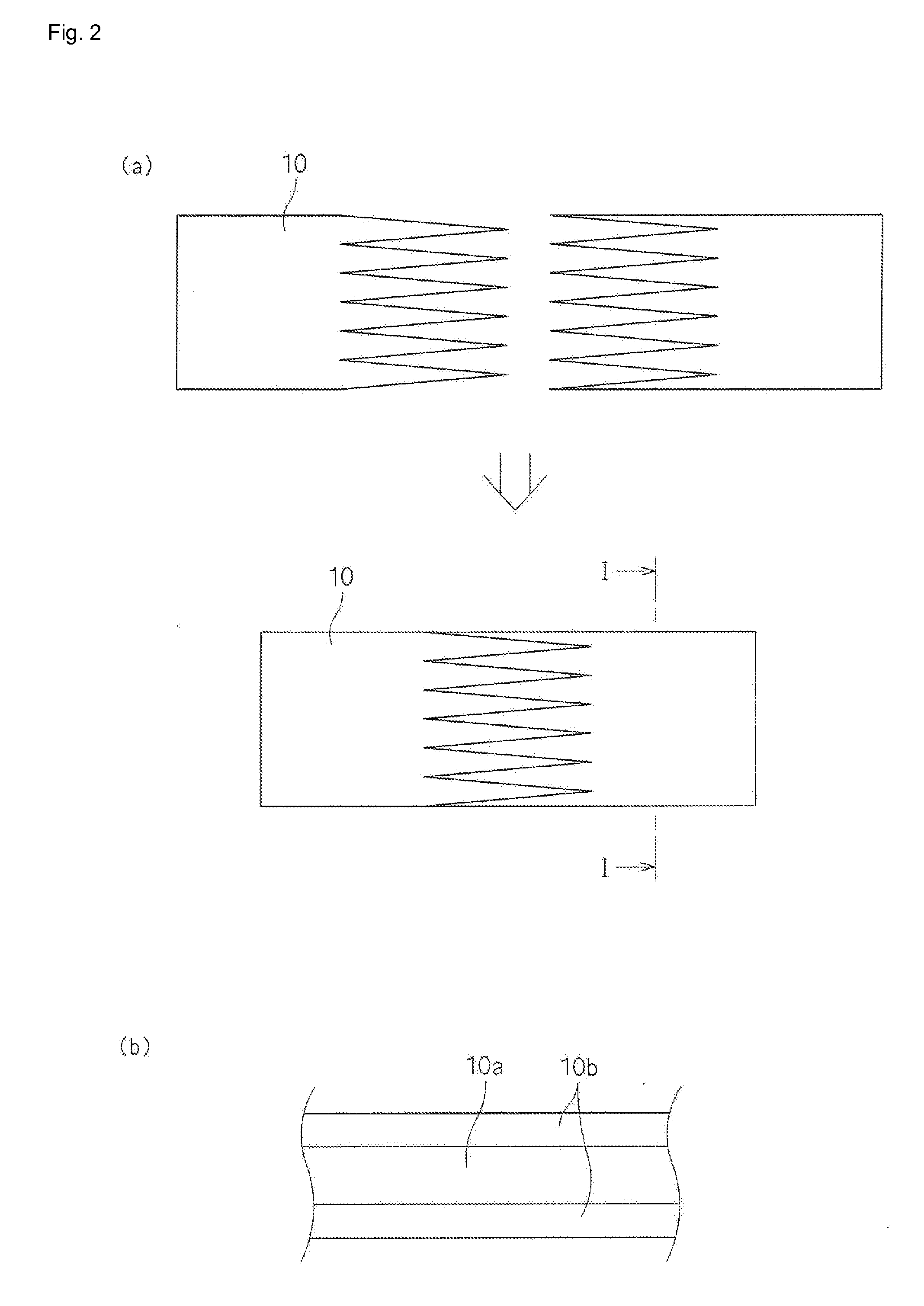
[0024]Firstly, the belt 10 cut by the belt processing tool of the present invention is described with reference to FIGS. 2(a) and 2(b).

[0025]The belt 10 shown in FIGS. 2(a) and 2(b) is an elongated sheet with a predetermined width, specifically a belt used for a belt conveyor, a conveyor device for a printing machine, or the like. The belt 10 is made up of a core material 10a, and an outer layer 10b laminated on both surfaces of the core material 10a, as shown in FIG. 2(b). The core material 10a is formed from a canvas, nonwoven fiber, or the like. The outer layer 10b is formed from natural rubber, various types of synthetic rubbers, or alternatively thermoplastic elastomer, or thermoplastic resin such as pol...


PUM

PropertyMeasurementUnit
Shapeaaaaaaaaaa

Abstract

A sheet cutter applied to a belt processing tool or the like is provided. The belt processing tool includes a mounting table 2 for mounting a belt thereon; a die holding plate 4 being ascendable and descendable with respect to the mounting table, and having a lower surface to which a Thomson die is fixed; a stripper plate 3 being installed ascendably and descendably above the mounting table, and pressing the upper surface of the belt during descent, and having a slit through which the blade of the Thomson die passes; an operation member including a planar cam and a lever for rotating the planar cam, the planar cam being fixed to the mounting table and pivotally supported on a rotary shaft, and moving up and down by rotation, and having a surface for pressing downward the die holding plate; a means for energizing upward the stripper plate; and a locking member for restricting the raised end of the stripper plate.

Description

TECHNICAL FIELD[0001]The present invention relates to a sheet cutter for cutting a sheet, such as a belt, into a predetermined shape, and to a belt processing tool. In particular, the present invention relates to a belt joint processing tool for forming an endless flat belt by joining together the end portions of a long flat belt.BACKGROUND ART[0002]Finger joint, in which the end portions of a belt are cut into a saw-tooth shape and are joined together, is employed to smoothly and strongly join together the end portions of the belt. The finger joint has the advantages of a large contact area between the end portions, and the enhanced strength of the joint. Patent document 1 describes a method of joining together a flat belt by the finger joint. According to this joint method, the end portions to be joined together are respectively processed into the saw-tooth shape, and are engagedly joined together (refer to FIG. 2).[0003]Patent document 2 discloses a motor-driven cutting machine. ...

Claims


Application Information

Patent Timeline
IPC IPC(8): B26D1/08B26D7/18B26F1/40
CPCB26D1/04B26D3/003B26D7/025B26D5/10B26D5/16B26D3/10Y10T83/215B26D1/08B26D1/06B26F1/40B26F1/44
Inventor KUBOTA, TAKESHI
Owner NITTA CORP
Learn More