Display apparatus
a technology of display apparatus and display screen, which is applied in the direction of static indicating device, instruments, optics, etc., can solve the problems of reducing the detection accuracy of touch positions, so as to prevent the display performance from lowering, the effect of simple structur
- Summary
- Abstract
- Description
- Claims
- Application Information
AI Technical Summary
Benefits of technology
Problems solved by technology
Method used
Image
Examples
first embodiment
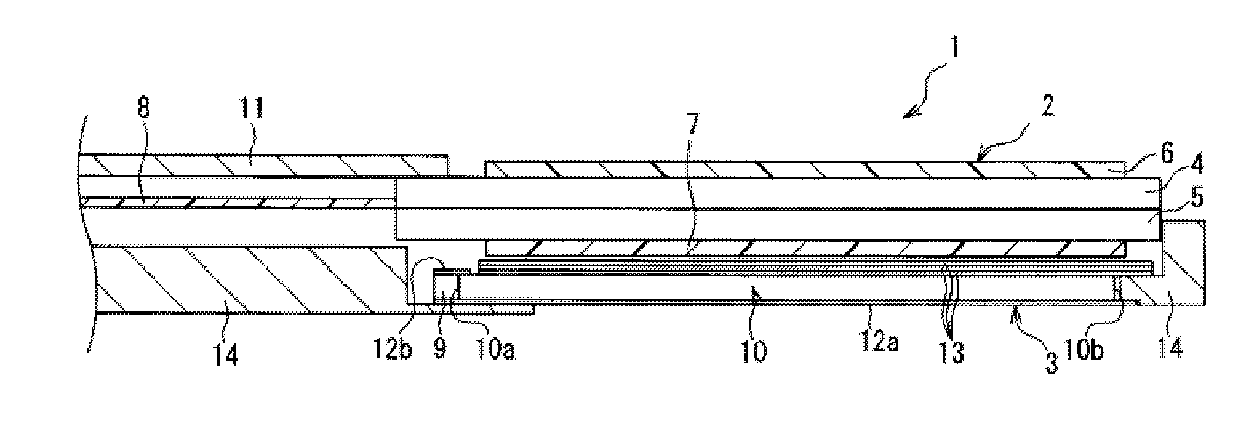
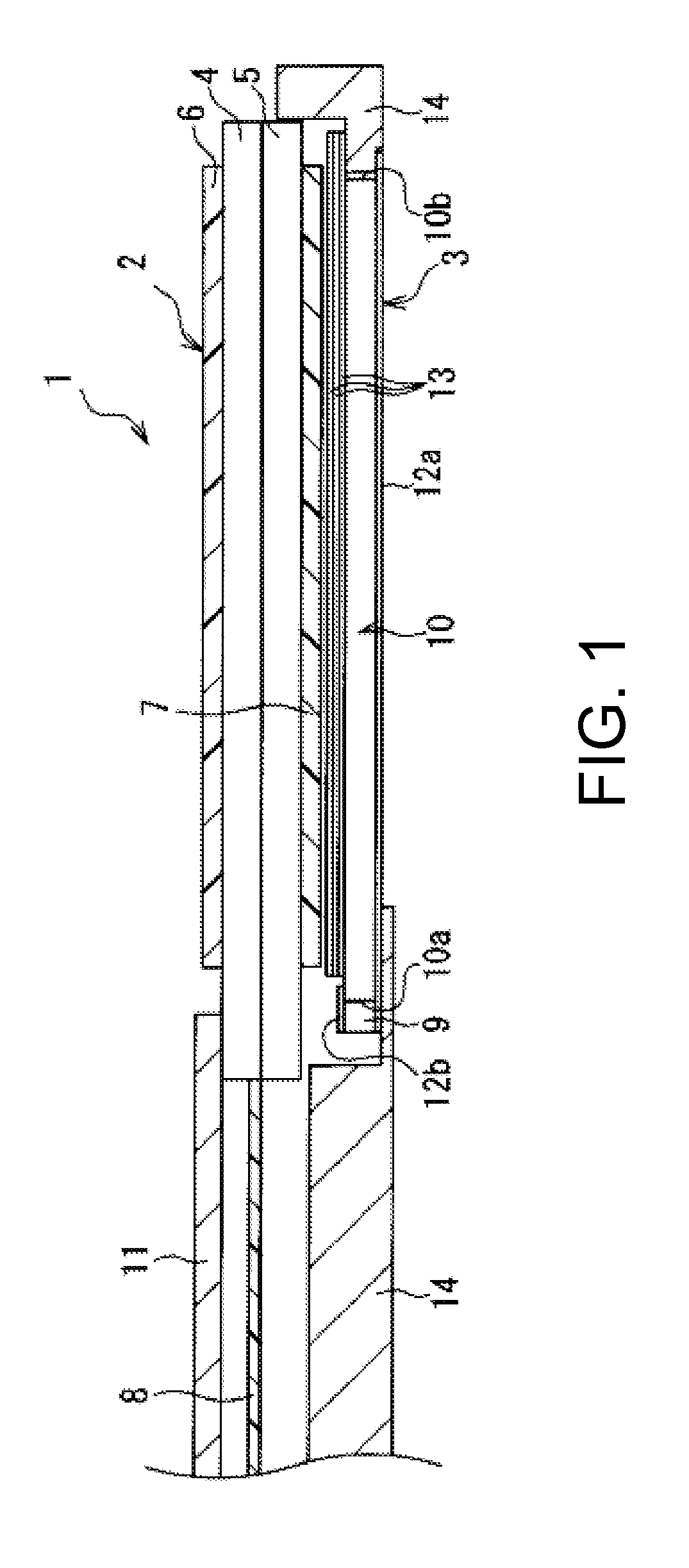
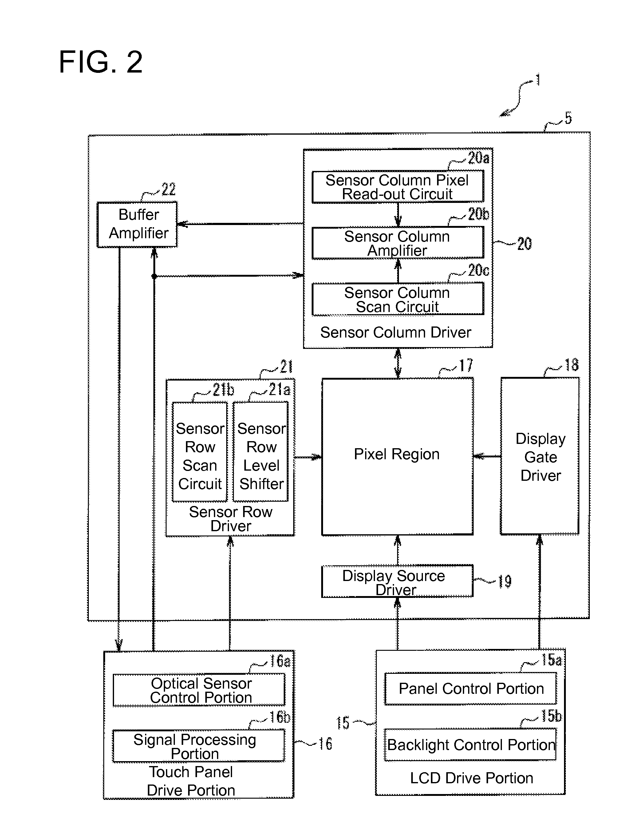
FIG. 1 is a schematic sectional view illustrating a liquid crystal display apparatus according to a first embodiment of the present invention. In FIG. 1, a liquid crystal display apparatus 1 of the present embodiment is provided with a liquid crystal panel 2 as a display portion that is installed with the upper side of FIG. 1 being taken as the viewing side (display surface side) and a backlight device 3 as a backlight portion that is disposed on the non-display surface side (lower side in FIG. 1) of the liquid crystal panel 2 and that irradiates this liquid crystal panel 2 with illumination light. Moreover, this liquid crystal display apparatus 1 has an integrated touch panel equipped with optical sensors (to be described later), so the liquid crystal display apparatus 1 is constructed such that this touch panel makes it possible to execute specified touch panel functions such as a user-operated input instruction detection action.
The liquid crystal panel 2 includes a color filter s...
second embodiment
FIG. 8 is a diagram illustrating a linear light-emitting diode unit in a liquid crystal display apparatus according to a second embodiment of the present invention; FIG. 8(a) is a perspective view of this linear light-emitting diode unit, and FIG. 8(b) is a plan view showing a configuration of essential parts of this linear light-emitting diode unit. In the figures, the main difference between the present embodiment and the aforementioned first embodiment is that two infrared light-emitting elements are sealed by a transparent resin on the substrate. Note that the elements that are in common with the aforementioned first embodiment are labeled with the same reference characters, and a redundant description thereof will be omitted.
Specifically, as exemplified in FIGS. 8(a) and 8(b), in the linear light-emitting diode unit 9′ of the present embodiment, five white light-emitting diodes 26 and four infrared light-emitting diodes 27′ are integrally provided on the substrate 28. In the li...
third embodiment
FIG. 9 is a schematic sectional view illustrating a liquid crystal display apparatus according to a third embodiment of the present invention. In the figure, the main difference between the present embodiment and the aforementioned first embodiment is that the linear light-emitting diode unit is disposed to each of the two mutually opposing side surfaces of the light guide plate. Note that the elements that are in common with the aforementioned first embodiment are labeled with the same reference characters, and a redundant description thereof will be omitted.
Specifically, as shown in FIG. 9, two linear light-emitting diode units 9 are disposed so as to respectively face the two mutually opposing side surfaces 10a and 10b of the light guide plate 10 in the liquid crystal display apparatus 1 of the present embodiment. With the liquid crystal display apparatus 1 of the present embodiment, white light from the white light-emitting diodes 26 and infrared light from the infrared light-em...
PUM
 Abstract
Description
Claims
Application Information
 - R&D
- Intellectual Property
- Life Sciences
- Materials
- Tech Scout
- Unparalleled Data Quality
- Higher Quality Content
- 60% Fewer Hallucinations
Browse by: Latest US Patents, China's latest patents, Technical Efficacy Thesaurus, Application Domain, Technology Topic, Popular Technical Reports.
© 2025 PatSnap. All rights reserved.Legal|Privacy policy|Modern Slavery Act Transparency Statement|Sitemap|About US| Contact US: help@patsnap.com


