Physically Unclonable Function Implemented Through Threshold Voltage Comparison

a threshold voltage and function technology, applied in the field of physical unclonable functions implemented through threshold voltage comparison, can solve the problem that the authentic device may not be able to authenticate itself, and achieve the effect of higher output voltag

Inactive Publication Date: 2011-12-29
GLOBALFOUNDRIES INC
View PDF6 Cites 134 Cited by
  • Summary
  • Abstract
  • Description
  • Claims
  • Application Information

AI Technical Summary

Benefits of technology

[0004]In a particular embodiment, an electronic device having a physically unclonable function is disclosed. The electronic device is operable to generate a response to a challenge. The electronic device includes a plurality of transistors, with each of the plurality of transistors having a threshold voltage substantially equal to an intended threshold voltage. The electronic device includes a challenge input configured to receive the challenge. The challenge includes one or more bits that are used to individually select each of a pair of transistors of the plurality of transistors. The electronic device also includes a comparator to receive an output voltage signal from each of the pair of transistors and to generate a response indicating which transistor of the pair of transistors has the higher output voltage. The output voltage of each of the pair of transistors varies as a result of variation in the threshold voltage of each of the pair of transistors.

Problems solved by technology

If the PUF is unstable, the authentic device may not always generate the same response in reply to a challenge and, as a result, an authentic device may be unable to authenticate itself.

Method used


Image

  • Physically Unclonable Function Implemented Through Threshold Voltage Comparison
  • Physically Unclonable Function Implemented Through Threshold Voltage Comparison
  • Physically Unclonable Function Implemented Through Threshold Voltage Comparison

Examples


Embodiment Construction

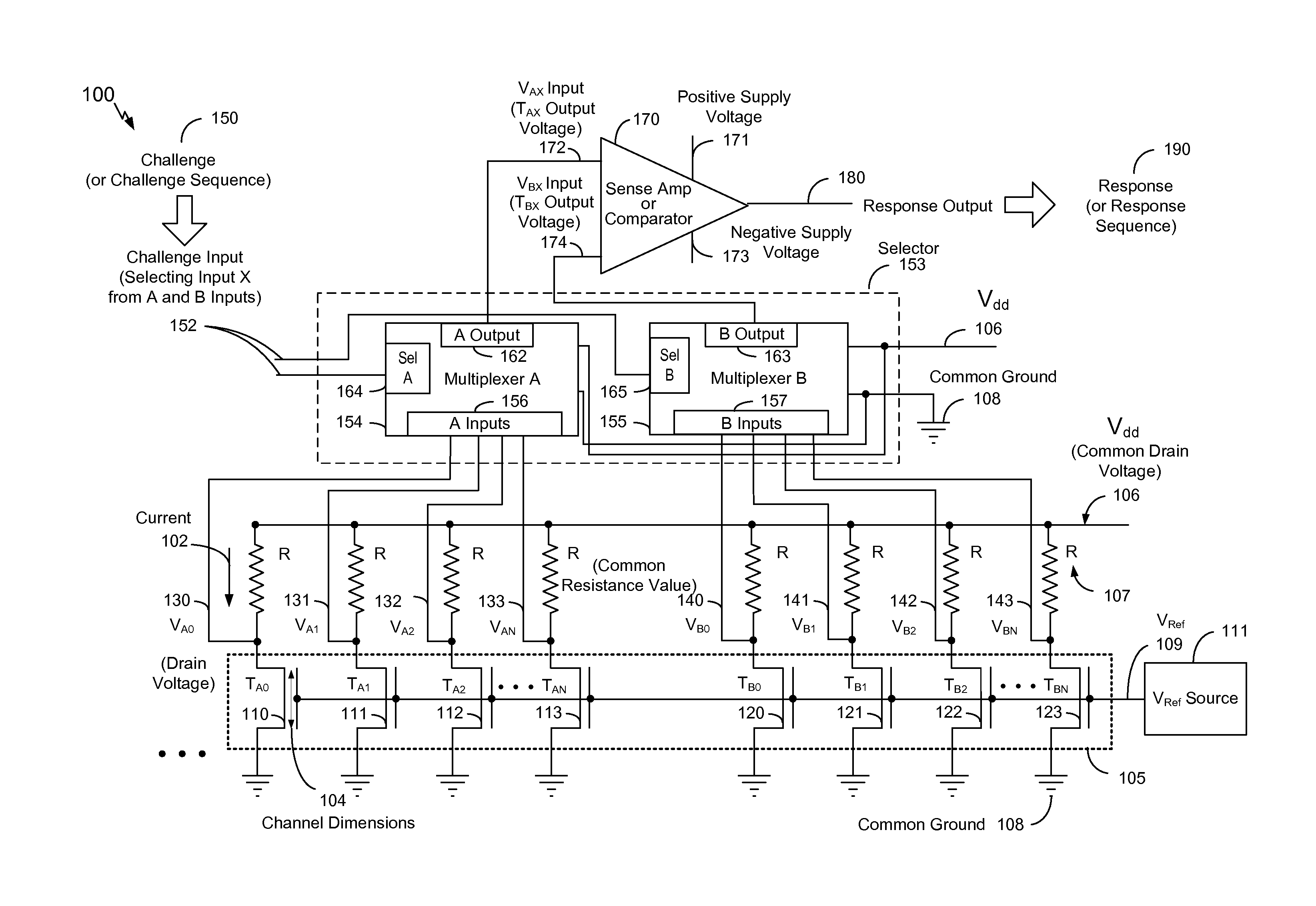
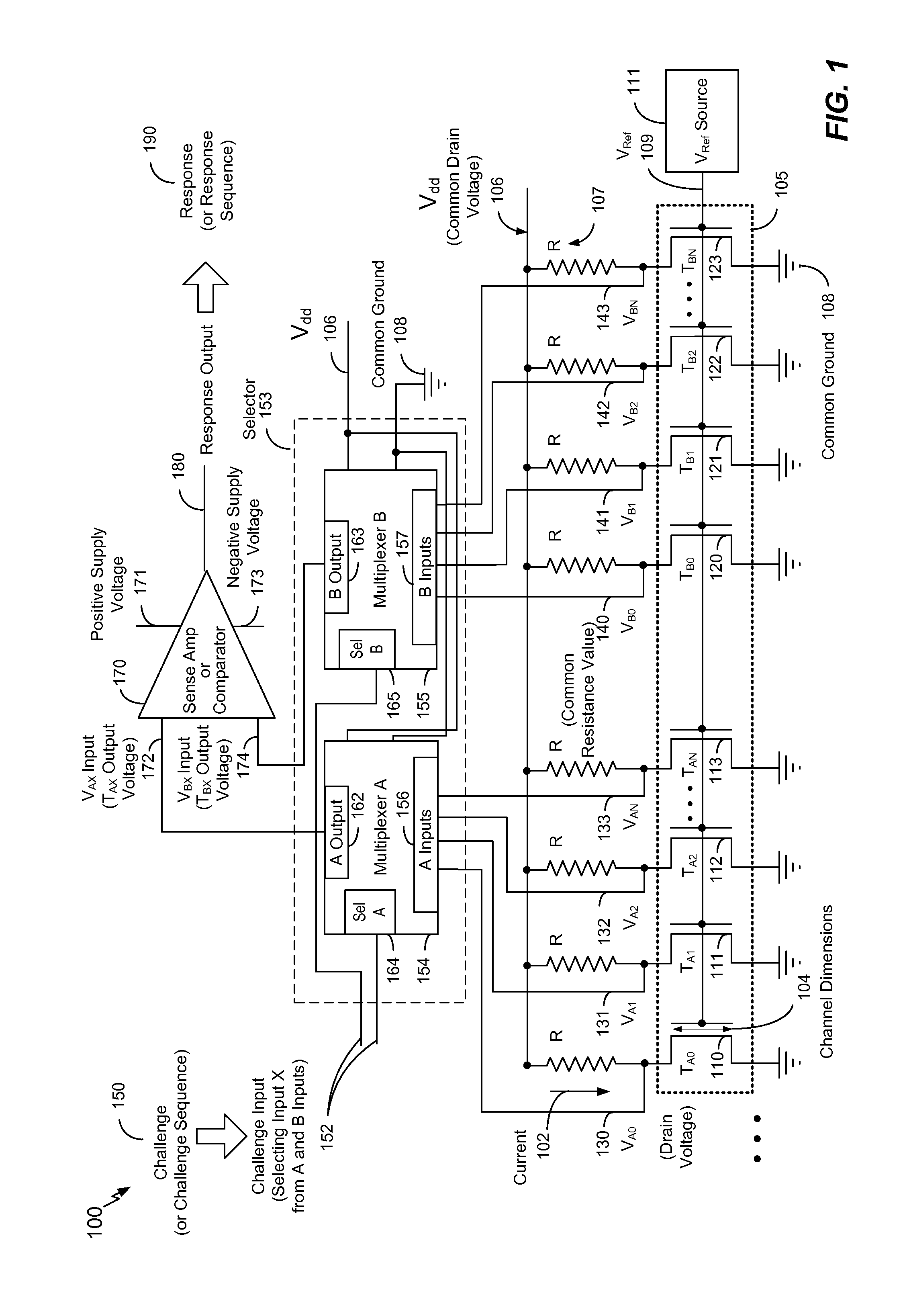
[0014]FIG. 1 is a block diagram of a particular illustrative embodiment of a device 100 including a physically unclonable function (PUF). The PUF is a result of a plurality of transistors 105 having varying threshold voltages as a result of process variations in their manufacture. The plurality of transistors 105 includes transistors TA0 110-TAN 113 and TB0 120-TBN 123. The transistors TA0 110-TAN 113 and TB0 120-TBN 123 are configured to have substantially equal threshold voltages at an intended threshold voltage level to provide a basis for the PUF, as further explained below. In one particular illustrative embodiment, the threshold voltage is regarded as being substantially equal to the intended threshold voltage if the threshold voltage is within a range of plus or minus 50 mV of the intended threshold voltage. Also in one particular illustrative embodiment, the plurality of transistors 105 includes n-channel metal oxide semiconductor (NMOS) field effect transistors (FETs). Chan...


PUM


Abstract

Electronic devices and methods are disclosed to provide and to test a physically unclonable function (PUF) based on relative threshold voltages of one or more pairs of transistors. In a particular embodiment, an electronic device is operable to generate a response to a challenge. The electronic device includes a plurality of transistors, with each of the plurality of transistors having a threshold voltage substantially equal to an intended threshold voltage. The electronic device includes a challenge input configured to receive the challenge. The challenge input includes one or more bits that are used to individually select each of a pair of transistors of the plurality of transistors. The electronic device also includes a comparator to receive an output voltage from each of the pair of transistors and to generate a response indicating which of the pair of transistors has the higher output voltage. The output voltage of each of the pair of transistors varies based on the threshold voltage of each of the pair of transistors.

Description

I. FIELD OF THE DISCLOSURE[0001]The present disclosure relates generally to device authentication, and, more specifically, to determining how a device may respond to a challenge according to a physically unclonable function (PUF) so as to authenticate the device.II. BACKGROUND[0002]A physically unclonable function (PUF) exploits variations, such as statistical process variation in manufacture or operation, to generate secret keys used in cryptographic operations, chip authentication, and even random number generation. A device that supports a PUF yields different responses to different challenge inputs. Authentication of a device using a PUF is performed by supplying a challenge input to the device to which the response of an authentic device is known. The response is a result of a function that, by definition, is not clonable. For example, a PUF may result from process variations in the production of otherwise identical devices. As a result of the process variations, the otherwise ...

Claims


Application Information

Patent Timeline
Patent Type & Authority Applications(United States)
IPC IPC(8): H04L9/20
CPCH04L9/3278H04L9/0866H04L9/08G06F21/73
Inventor FICKE, JOEL T.HALL, WILLIAM E.HOOK, TERENCE B.SPERLING, MICHAEL A.WISSEL, LARRY
Owner GLOBALFOUNDRIES INC
Why Eureka
Try Eureka