Drill tip and drilling tool having a drill tip

Active Publication Date: 2011-12-29
KENNAMETAL INC
View PDF6 Cites 35 Cited by
  • Summary
  • Abstract
  • Description
  • Claims
  • Application Information

AI Technical Summary

Benefits of technology

[0005]The invention is based on the object of rendering possible a drilling tool t

Problems solved by technology

This is because, in the case of symmetrical drills, vibrations of the drilling tool increase during the drilling operation because of the symmetry and, as it were, “build up”, such that, because of the vibrating of the drilling tool, irregularities, also termed “chatter marks”

Method used


Image

  • Drill tip and drilling tool having a drill tip
  • Drill tip and drilling tool having a drill tip
  • Drill tip and drilling tool having a drill tip

Examples


Embodiment Construction

[0030]In the figures, parts that have the same function are denoted by the same references.

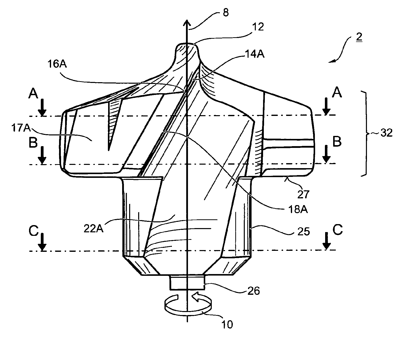
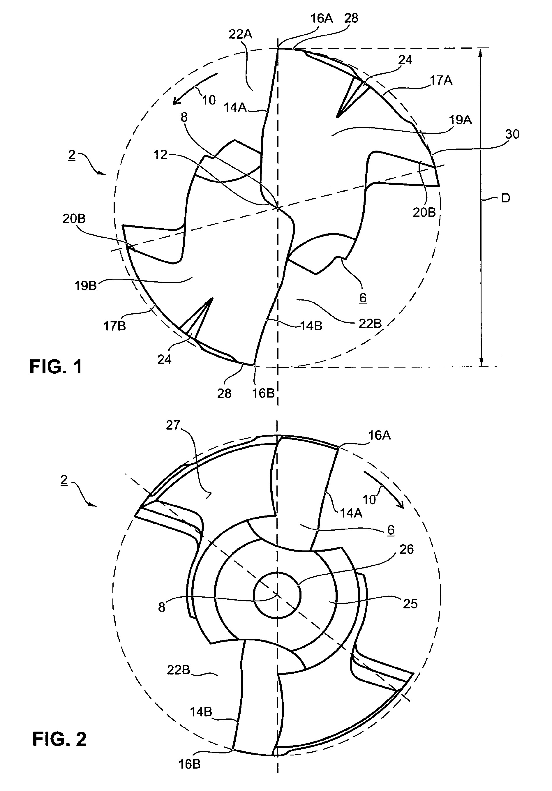
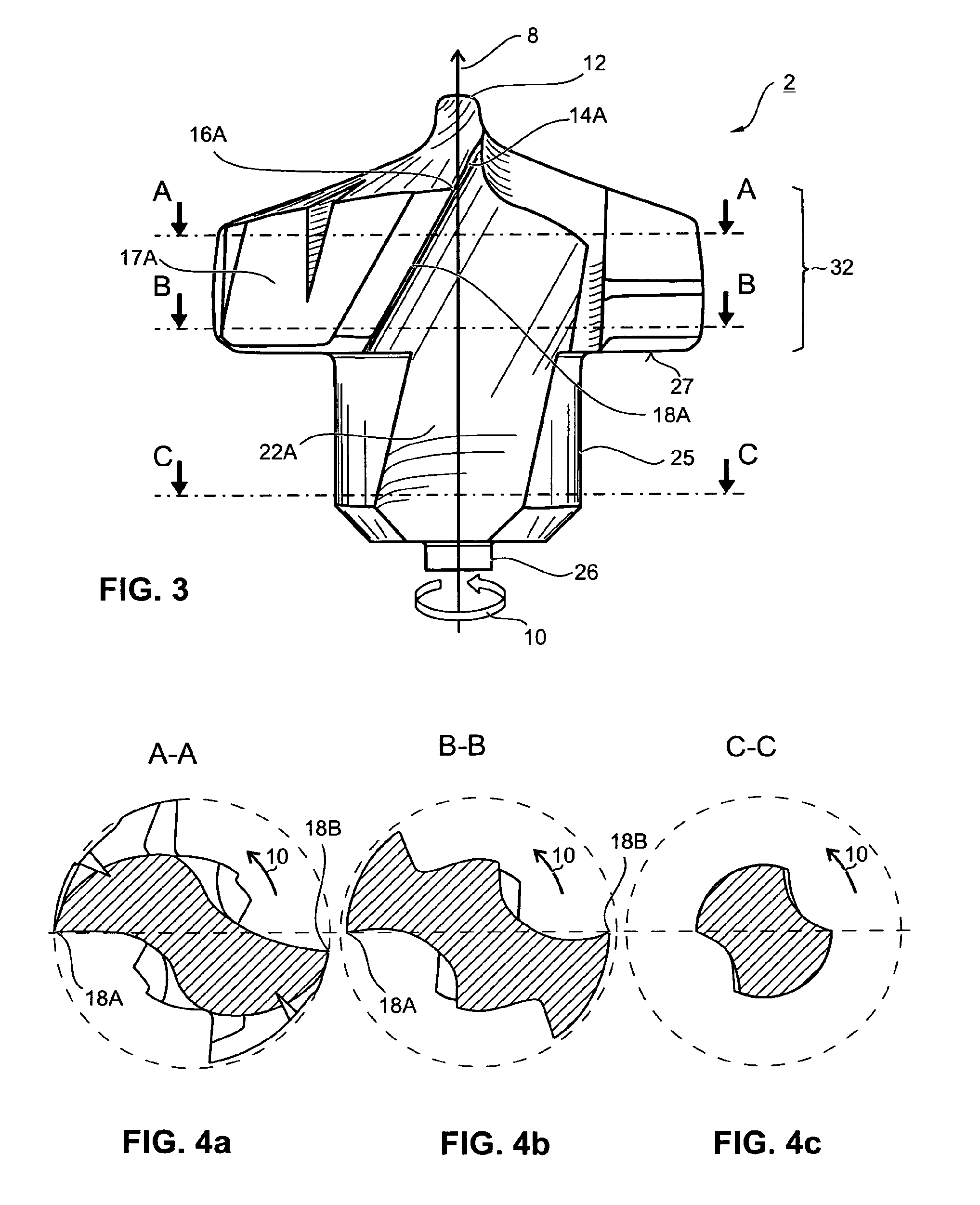
[0031]The drill tip 2 according to FIGS. 1 to 3 is realized as an exchangeable modular part that can be inserted in a drill basic body 4, as represented in FIG. 5, and that, together with the latter, constitutes a drilling tool 5. In the exemplary embodiment, the drill tip 2 is realized as a single piece, and has a specially shaped basic body 6. It is thus constituted by this basic body 6. The drill tip 2 has an axis of rotation 8, which, during operation, is at the same time the rotary axis about which the entire drilling tool 5 rotates in the direction of rotation 10.

[0032]At its front outside end, the drill tip 2 has a chisel edge 12, which crosses the axis of rotation 8 and in each case undergoes a transition into a main cutting edge 14A,B, which run outwards in the radial direction and end at a cutting corner 16A,B. Starting from the respective cutting corner 16A,B, a respective secondary...


PUM

PropertyMeasurementUnit
Areaaaaaaaaaaa
Distanceaaaaaaaaaa
Levelaaaaaaaaaa

Abstract

The invention relates to a drill tip (2) comprising a base body (6) having chip flutes (22A,B) and extending in the axial direction along an axis of rotation (8) and having at least two main cutting edges (14A,B) on the front face thereof extending outward in the radial direction to a cutting corner (16A,B). Seen in cross section, the base body is asymmetric relative to rotation about the axis of rotation (8) at the height of the cutting corner (16A,B). The cross section of the base body is simultaneously designed having symmetrical spacing from the main cutting edges (14A,B). The drill tip (2) is in particular designed as an interchangeable modular part of a modularly designed drill tip (5). A drill base body (4) in which the drill tip (2) can be inserted can therefore in turn be designed symmetrically.

Description

BACKGROUND OF THE INVENTION[0001]The invention relates to a drill tip according to the preamble of Claim 1, and to a drilling tool having such a drill tip.[0002]A drill tip according to the preamble of Claim 1 is disclosed, for example, by DE 10 2006 025 294 A1. Described therein is a drilling tool of a special asymmetrical configuration. The drill tip of this drilling tool has two main cutting edges, which—unlike a symmetrical configuration—are disposed in a non-rotationally symmetrical manner relative to a 180° rotation about the axis of rotation of the drilling tool. The main cutting edges extend as far as a cutting corner adjoined in each case by a secondary cutting edge, which runs along a chip flute. At the periphery, on the so-called drill heel, a guide land adjoins the respective secondary cutting edge. In addition, it is provided that an additional support land for only one of the two chisel edges is realized on the drill heel. By means of the support land, the drilling too...

Claims


Application Information

Patent Timeline
IPC IPC(8): B23B51/02B23B51/00
CPCB23B51/02B23B2251/02B23B2251/046B23B2251/282Y10T408/892B23B2251/446B23B2251/50B23B2251/70Y10T408/9095B23B2251/408B23B51/00B23B2251/085B23B2251/40
Inventor SCHWAGERL, JURGENKAUPER, HERBERT RUDOLF
Owner KENNAMETAL INC
Why Eureka
Try Eureka