Ground flare

a flare and ground technology, applied in the field of ground flares, can solve the problems of high cost of refractory material that forms the incinerator main body, unsuitable flammable exhaust gas for gas turbine fuel, and high cost of air blower b>2/b>, and achieve the effect of preventing resonating and vibrating

Inactive Publication Date: 2011-12-29
HOKKAIDO ELECTRIC POWER COMPANY +12
View PDF9 Cites 5 Cited by
  • Summary
  • Abstract
  • Description
  • Claims
  • Application Information

AI Technical Summary

Benefits of technology

[0039]According to the present invention described above, a low-frequency vibration generated from a ground flare can be set below a fixture-vibration generation limit, and thus, the surrounding objects can be prevented from resonating and vibrating.

Problems solved by technology

An example of a flammable gas to be burned by such processing apparatuses is a gas generated by gasifying coal in an integrated coal gasification combined cycle (IGCC) at the initial activation of the plant, which is a flammable exhaust gas unsuitable for gas turbine fuel.
In this case, there are problems in that the cost of the refractory material that forms the incinerator main body 1 and the cost of the air blower 2 are high.
However, flames are exposed, and thus, the problems of occurrence of fire due to radiating the surroundings, noise due to the combustion sound of the flames, and lack of visual harmony due to the fact that the flames can be viewed have been noted.

Method used


Image

  • Ground flare
  • Ground flare
  • Ground flare

Examples


first embodiment

Shifting Natural Frequency to Higher Pitch

[0085]An embodiment described below shifts the natural frequency of a low-frequency sound generated from the ground flare tower to a higher pitch to prevent resonance with the natural frequency of burner combustion.

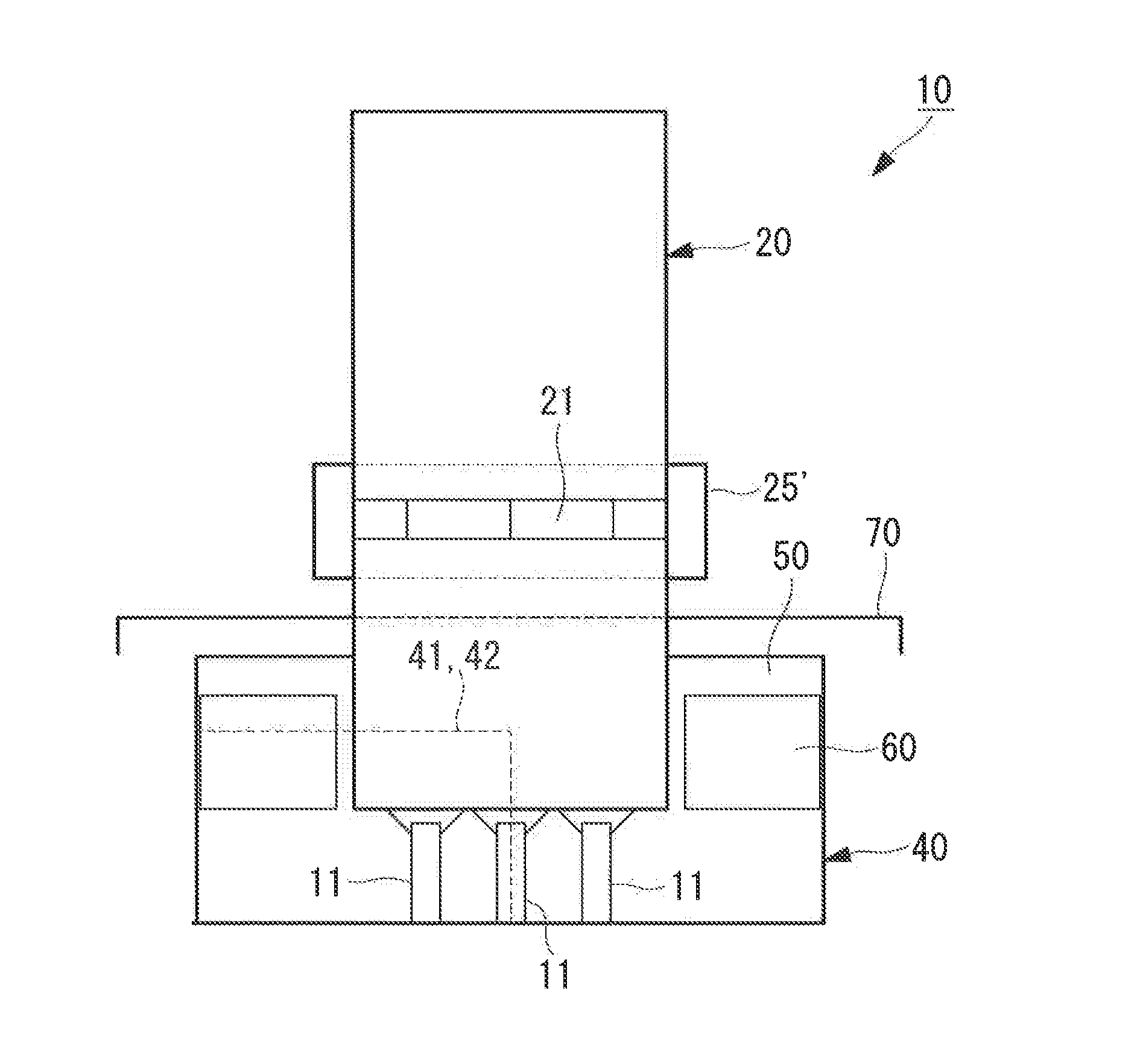
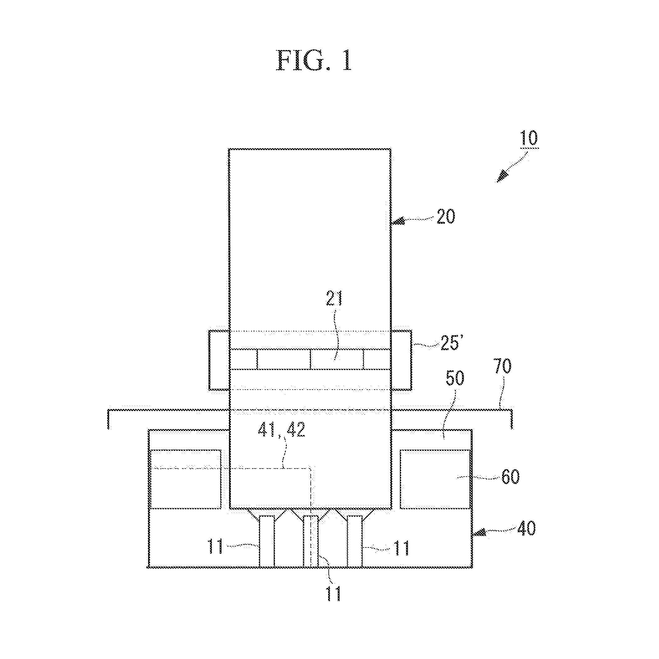
[0086]A ground flare 10A shown in FIG. 3 changes the natural frequency by providing windbreak openings 41 at part of the windbreak 40 and closing the windbreak openings 41 with non-wall sheets 42. That is, after part of the windbreak 40 is cut out to form the windbreak openings 41, the non-wall sheets 42 are mounted over the windbreak openings 41 to close them. The non-wall sheets 42 used here break the wind and prevent an audible sound from leaking out, and also prevent, flames from being viewed from the outside through the windbreak openings 41, and should be formed of a material, that does not function as a wall against a low-frequency sound.

[0087]The windbreak openings 41 provided by removing part of the windbreak 40 are desir...

second embodiment

Shift of Natural Frequency to Lower Pitch

[0116]An embodiment described below shifts the natural frequency of a low-frequency sound generated from the ground flare tower to a lower pitch to prevent resonance with the natural frequency of burner combustion. That is, as shown in FIG. 12A to FIG. 15, the windbreak portion is extended to decrease a frequency to be generated, and the sound pressure level of a low-frequency noise is reduced.

[0117]In this method, the burner position ç′ of the burners 11, which is found using FIG. 15 and [Formula 1] shown below, falls within a range of 2.2 to 3.4 from the inlet Wi of a windbreak 40A with respect to a length (entire guide length) including the chimney 20 and the windbreak 40A.

ϛ′=(1-L1+0.6d1c2×f)×4(Formula1)[0118]L1: chimney height (m)[0119]d1: chimney diameter (m)[0120]c: velocity of sound (m / s)[0121]f: measured frequency (Hz)

[0122]In. [Formula 1], L1 is chimney height (m), d1 is the diameter of the chimney (m), c is the velocity of sound (m / ...

third embodiment

Multiple Towers

[0127]An embodiment described below adopts multiple ground flare towers and combines towers having different dominant frequencies to reduce the sound pressure level.

[0128]This embodiment is provided with two separated ground flares 10a and 10b so as to satisfy the required capacity, as shown in FIG. 16, for example. In this case, the two separated ground flares 10a and 10b are set so that the respective dominant frequencies differ by changing the chimney lengths of chimneys 20a and 20b; the dominant frequency of the ground flare 10b, having a long air column, produces a low-pitched sound, and the dominant frequency of the ground flare 10a, having a short air column, produces a high-pitched sound. That is, the two ground flares 10a and 10b having different primary frequencies are placed side by side. In this example of separation, both the chimney and the windbreak are separated into two. Reference signs 40a and 40b in the drawing denote windbreaks.

[0129]Disposing the ...


PUM


Abstract

Provided is a ground flare in which a low-frequency vibration generated from a ground flare tower, such as a chimney, is properly adjusted to suppress it below a fixture-vibration generation limit, thereby preventing surrounding objects from resonating and vibrating. In a ground flare that burns a flammable exhaust gas with a burner at the lower end of a chimney, in which the lower end of the chimney and the periphery of the burner are surrounded by a windbreak, the low-frequency-noise sound pressure level of a ground flare tower composed of the chimney and the windbreak is reduced by selecting at least one of changing a natural frequency generated from the ground flare tower, using multiple ground flare towers, and installing a low-frequency-vibration absorber in the ground flare tower.

Description

TECHNICAL FIELD[0001]The present invention, relates to a ground flare for use in burning a flammable exhaust gas.BACKGROUND ART[0002]Conventionally, processing apparatuses that burn a flammable as are roughly classified into three types: incinerators, open flare stacks, and ground flare stacks (ground flares).[0003]An example of a flammable gas to be burned by such processing apparatuses is a gas generated by gasifying coal in an integrated coal gasification combined cycle (IGCC) at the initial activation of the plant, which is a flammable exhaust gas unsuitable for gas turbine fuel. The integrated coal gasification combined cycle is a cycle for generating electricity by gasifying coal serving as a fuel to operate a gas turbine and using the driving force of the gas turbine and exhaust heat from the gas turbine.[0004]An incinerator (see FIG. 24) is an apparatus that burns a flammable gas with an air blower 2 provided for an incinerator main body 1 formed of a refractory material or ...

Claims


Application Information

Patent Timeline
Patent Type & Authority Applications(United States)
IPC IPC(8): F23G7/08
CPCF23D2210/00F23M20/005F23J2900/13003F23G7/085F23G7/06F23G7/08
Inventor YOKOHAMA, KATSUHIKOHONDA, IWAOSUGANUMA, NAOKIANDO, HIROFUMIYOSHIDA, NAOSHIGEHORIE, YOSHIHIKOTERADA, HITOSHIKAWAI, TORUKIMURA, ATSUSHI
Owner HOKKAIDO ELECTRIC POWER COMPANY
Why Eureka
Try Eureka