Method and apparatus for the diagnosis and prognosis of active implants in or attached to biological hosts or systems

a technology of active implants and biological hosts, applied in the direction of nuclear elements, instruments, radiation therapy, etc., can solve the problems of inability to effectively reconstruct original signals, degradation, failure, and many and complex nuances of monitoring, diagnosing and predicting the functionality of electronic devices, and achieve the effect of diagnostic and prognostic methods and apparatus

Active Publication Date: 2011-12-29
NOKOMIS
View PDF7 Cites 25 Cited by
  • Summary
  • Abstract
  • Description
  • Claims
  • Application Information

AI Technical Summary

Benefits of technology

[0046]A further object of the invention is to provide a diagnostic and prognostic method and apparatus that is enhanced by distribution of continually updated electronic implant device history models to client databases in an automated fashion.
[0047]Yet another object of the invention is to provide a diagnostic and prognostic method and apparatus that is enhanced by the transfer of specific device history between client databases of specific device history models to allow for changes in geography of biological hosts.
[0048]It is an object of the invention to provide a method and apparatus that is enhanced by updating local and master device degradation models based on newly discovered degradation modes.

Problems solved by technology

The nuances of monitoring, diagnosing, and predicting electronic device functionality, degradation, and failure are numerous and complex.
This complexity is compounded by device interaction with biological hosts.
These various references cite biological tissues' ability to attenuate and distort electromagnetic radiation, but none provide a way to effectively reconstruct an original signal.
Signal distortion is particularly evident in electronically enabled medical implants and animal tracking implants, where great pains are taken to place the device transceiving antennas or coils close to the interface between the biological host and free space.

Method used


Image

  • Method and apparatus for the diagnosis and prognosis of active implants in or attached to biological hosts or systems
  • Method and apparatus for the diagnosis and prognosis of active implants in or attached to biological hosts or systems
  • Method and apparatus for the diagnosis and prognosis of active implants in or attached to biological hosts or systems

Examples


first envisioned embodiment

DESCRIPTION OF FIGURE ELEMENTS FOR A FIRST ENVISIONED EMBODIMENT

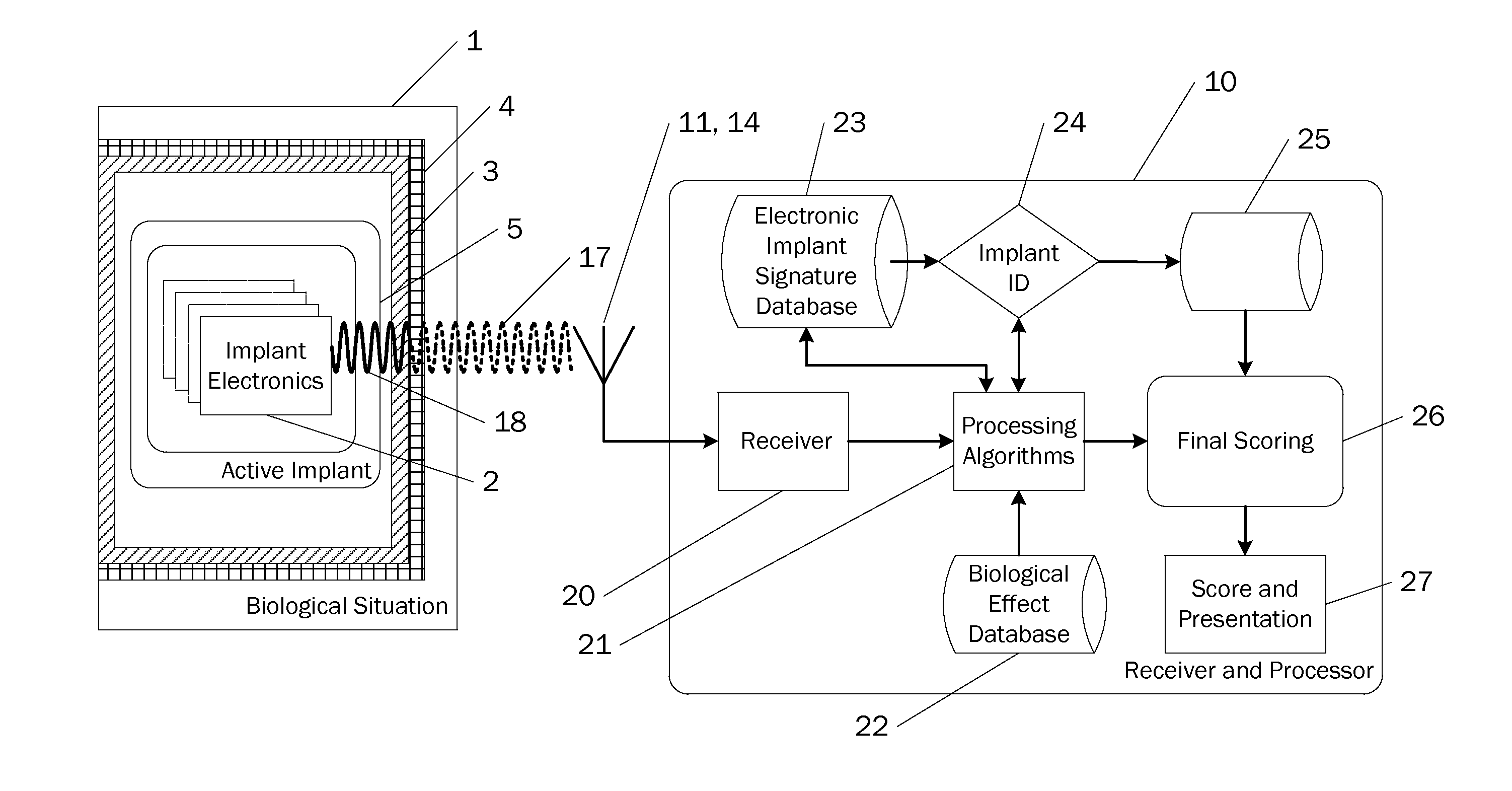
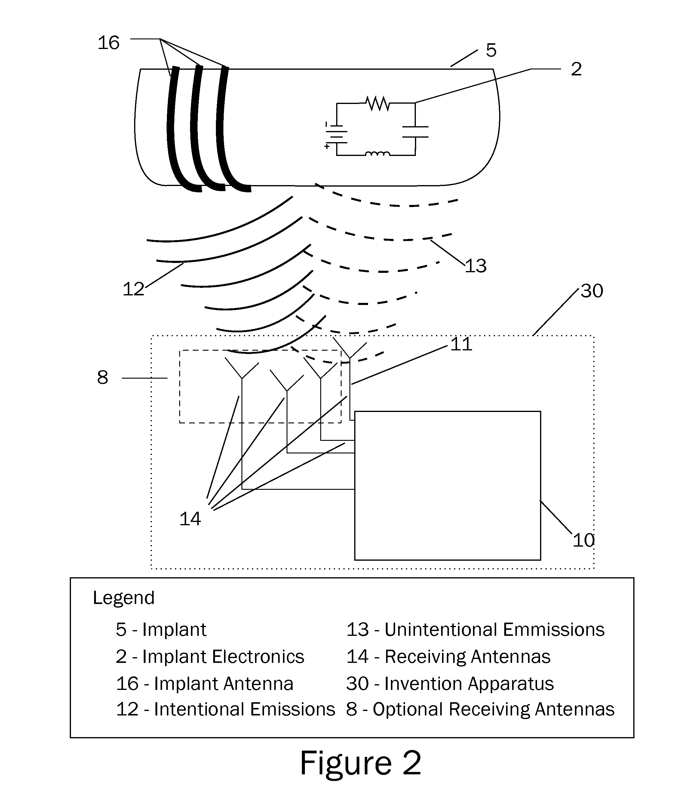
[0076]Referring now to the invention in more detail, in FIG. 1, FIG. 2, FIG. 5, and FIG. 8 there is shown a signal processor 10 that collects at least one of the intentional emissions 12 and unintentional emissions 13 emitted by substantially all electronic devices regardless of implantation in or attachment to any biological host. One or more of the intentional emissions 12 and unintentional emissions 13 make up generated emissions 18 that are influenced by biological situation 1 and become raw emissions 17.

[0077]Referring to FIG. 1, FIG. 2, FIG. 3, FIG. 5, and FIG. 7 there is shown active implant 5 that is another object of this invention. Implant electronics 2, integral to active implant 5, are the ultimate source of raw emissions 17 from which information is extracted to accomplish the goals of this invention.

[0078]Said raw emissions 17, shown in FIG. 1 and FIG. 2, are the results of generated emissions 18 interacti...

second envisioned embodiment

DESCRIPTION OF FIGURE ELEMENTS FOR A SECOND ENVISIONED EMBODIMENT

[0086]Referring now to the invention in more detail, in FIG. 7 is shown second embodiment of means to accomplish the objects of this invention. Still referring to FIG. 7, there is shown local signal processor 60, antenna array 61 comprising (without limitation) two complementary antennas attached to non-biological host aware per antenna receiver 62 and biological host aware per antenna receiver 63. Biological host aware per antenna receiver 63 is informed by biological effect data stored in biological effect database 65 and selected by a priori information 64 to eliminate biological effects induced by biological situation 1. The output of non-biological host aware per antenna receiver 62 and biological host aware per antenna receiver 63 is combined into the input of local multi-channel information aggregator 67. Multi-channel information aggregator 67 combines the output of non-biological host aware per antenna receive...


PUM


Abstract

A method and apparatus to measure and analyze electromagnetic emissions from implanted electronics to accomplish at least one of: detect and identify an active implant comprising electronics implanted in a biological host, diagnose the health of individual electronics as well as their health as an ensemble, and predict probable degradation of individual electronics, degradation of the electronic ensemble, and of the active implant in an automated fashion. The methods comprise filtering techniques to extract the information about the active implant's electronics by filtering out relevant biological effects induced by the active implant's biological situation. Said detection, identification, diagnosis, and prognosis are based on the measurement of intentional and unintentional electromagnetic emissions that emanate from the implant electronics of the active implant in a given biological situation.

Description

CROSS-REFERENCE TO RELATED APPLICATIONS[0001]This patent application is related to and claims priority from U.S. Provisional Patent Application Ser. No. 61 / 398,513 filed Jun. 28, 2010 and is herein incorporated by reference.FIELD OF THE INVENTION[0002]The present invention is in the technical field of monitoring, diagnosis, and prognosis of electrically enabled devices. More particularly, the present invention is in the technical field of monitoring, diagnosis, and prognosis of electrically enabled devices implanted in or attached to biological hosts or systems using the unintended electromagnetic emissions of said electrically enabled devices.BACKGROUND OF THE INVENTION[0003]The nuances of monitoring, diagnosing, and predicting electronic device functionality, degradation, and failure are numerous and complex. This complexity is compounded by device interaction with biological hosts. The literature is full of different electrical models of biological tissues described for specific ...

Claims


Application Information

Patent Timeline
Patent Type & Authority Applications(United States)
IPC IPC(8): G06F15/00G06F17/40
CPCA61N1/37223A61N2001/37294A61N1/37282A61N1/37229
Inventor PATHAK, BOGDAN AMARUKELLER, III, WALTER J.
Owner NOKOMIS
Why Eureka
Try Eureka