
Optically Redundant Fire Detector for False Alarm Rejection

Active Publication Date: 2012-01-05
TYCO FIRE PRODS LP
View PDF106 Cites 30 Cited by
  • Summary
  • Abstract
  • Description
  • Claims
  • Application Information

AI Technical Summary

Benefits of technology

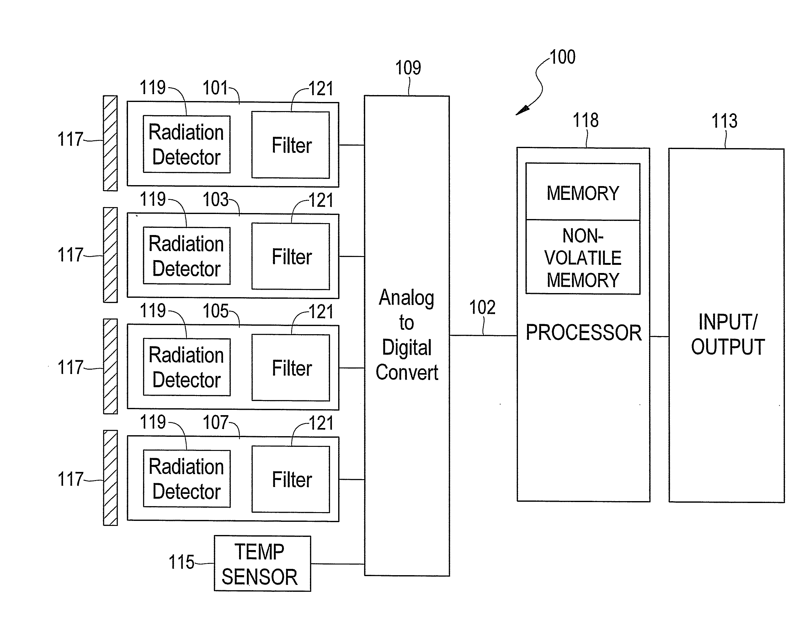
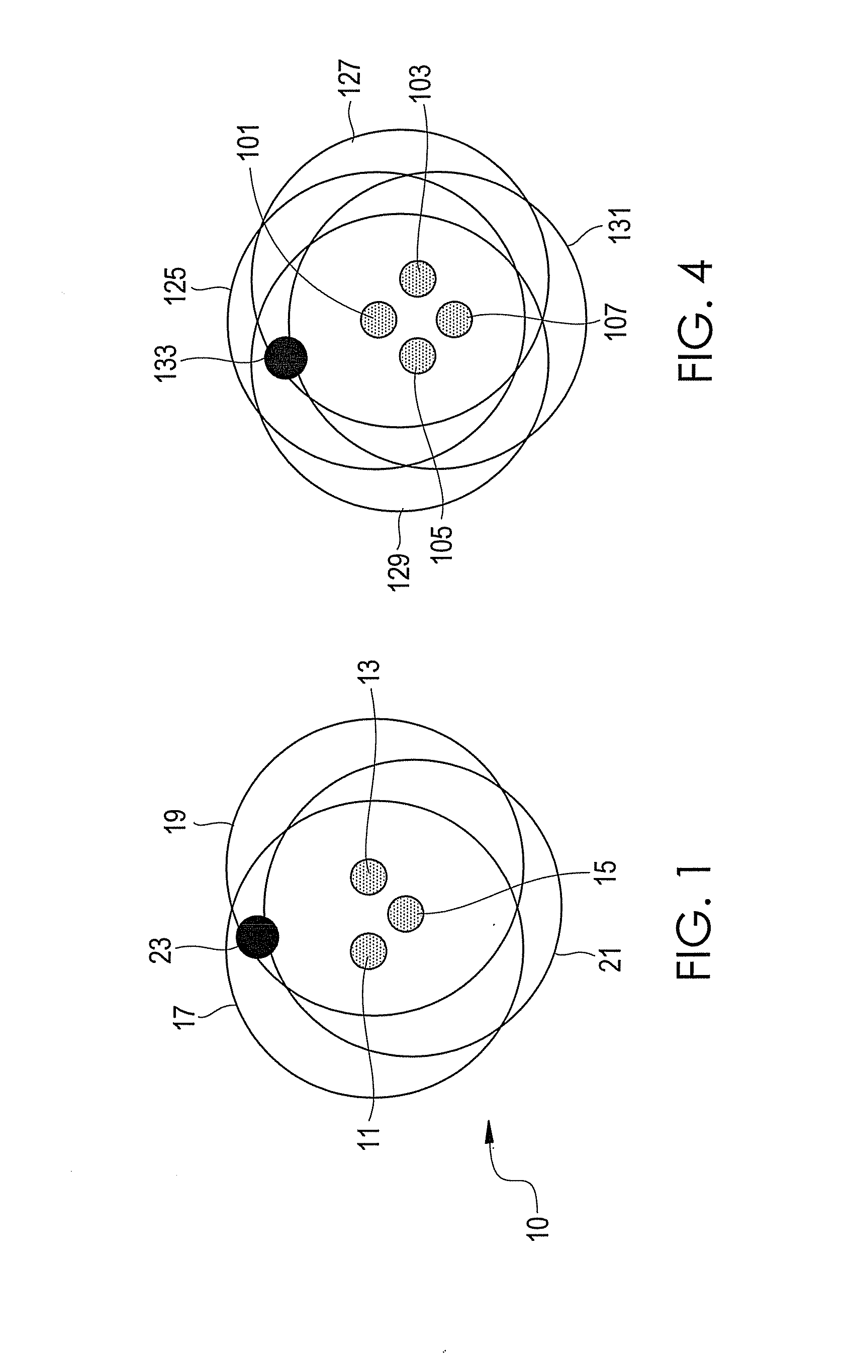
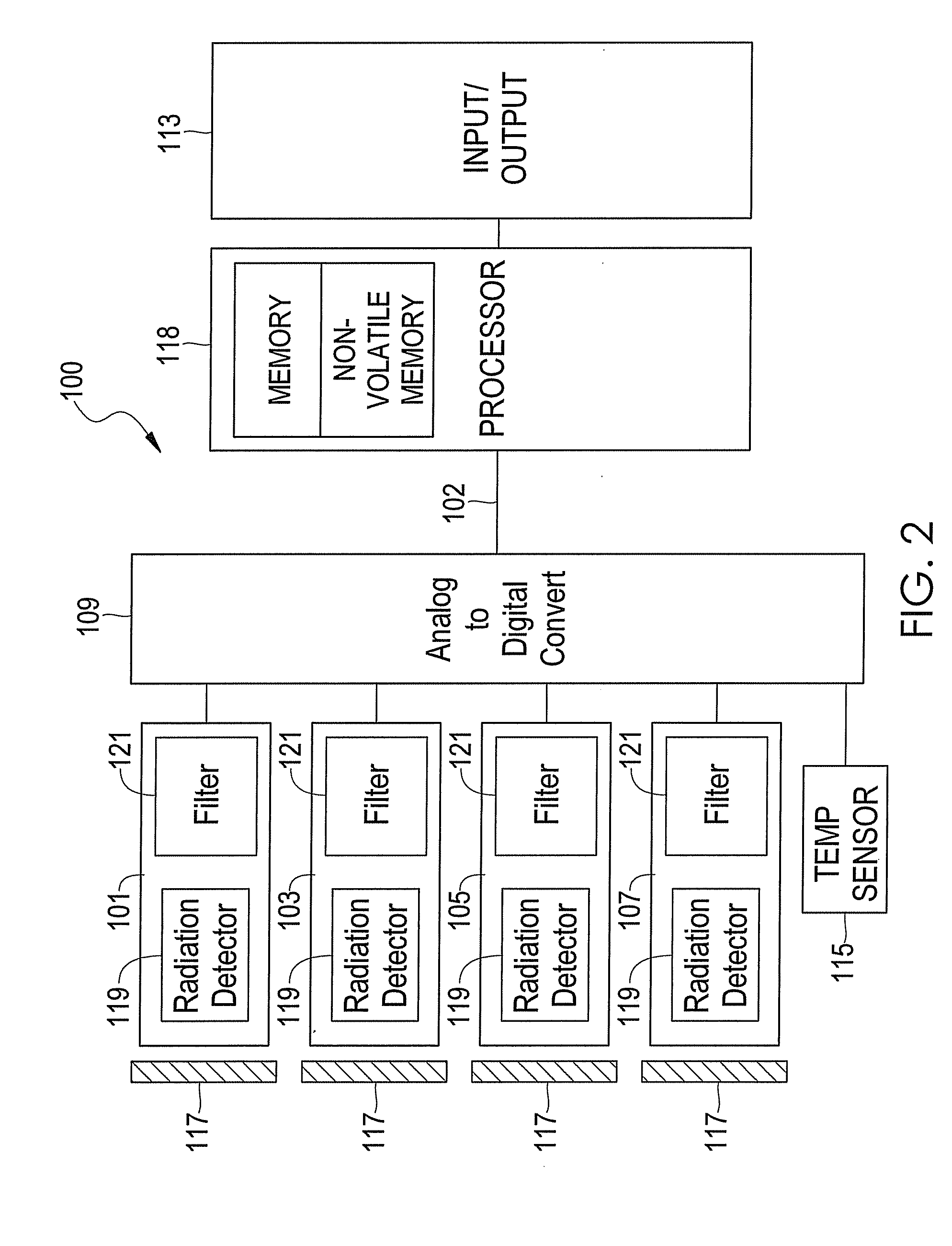
[0005]The present invention is directed to a system for confirming the detection of a fire using a fire detection system having a plurality of flame sensors each equipped with a radiation detector and an optical filter having a spectral transmission characteristic in which at least one optical filter is redundant to at least one other optical filter. The present invention is further directed to a method for testing for the condition in which a spatially small source of radiation is in close proximity to a flame detector so that the multiple radiation sensors of the detector each view different spatial extents of the object so that a false alarm is avoided. As such, the present invention is particularly suited for detecting fires where low false alarms rates are required and the distance and size of the fire varies over a wide range.

Problems solved by technology

However, if the first and second output are not sufficiently similar or they do not meet the predetermined fire-presence criteria, the system will not transmit the fire alarm command signal, even if the first output indicates the presence of a fire event.

Method used


Image

  • Optically Redundant Fire Detector for False Alarm Rejection
  • Optically Redundant Fire Detector for False Alarm Rejection
  • Optically Redundant Fire Detector for False Alarm Rejection

Examples


examples

[0025]A fire detection system having an operationally redundant flame sensor is described where the redundant flame sensor is structurally different from but substantially similar in performance to the flame sensor it mimics. In particular, the fire detection system includes three optical flame sensors. One of these sensors is chosen to be mimicked by a fourth optical flame sensor. In theory, any one of the three flame sensors could be chosen to be mimicked. However, it is preferred that the flame sensor that, in general, has the highest signal to noise ratio is mimicked. This flame sensor can be mimicked using various approaches that are functionally different and then implementing some form of compensation to make the operationally redundant flame sensor operate in a substantially similar fashion to the flame sensor chosen for mimicry.

[0026]In this manner, a Geiger-Mueller sensor and a UV-enhanced Silicon sensor, or a Lead-Selenide sensor and a thermopile sensor could be made oper...


PUM


Abstract

A system for confirming the detection of a fire using a plurality of radiation or flame sensors each equipped with a radiation detector and an optical filter having a spectral transmission characteristic in which at least one optical filter is redundant to at least one other optical filter. The result is a system having operationally redundant sensors. In use, if a fire is detected by one of the redundant sensors without including the other redundant radiation sensor in the fire detection calculation, then a fire detection algorithm can switch to the other operationally redundant sensor to check for confirmation of a fire. Due to the spatial separation and if the object is small and close, a different result will be obtained with the redundant detector being used in the calculation compared to the primary detector that is associated with the redundant detector.

Description

FIELD OF THE INVENTION[0001]The present invention is generally directed to a system and method for confirming the detection of a fire in a monitored region. More particularly, the present invention is directed to a fire detection system including an operationally redundant flame sensor and logic for discriminating between a fire event and a false fire event in a monitored region.BACKGROUND OF THE INVENTION[0002]Optical fire detection systems including multiple flame sensors are known in the art. Exemplary systems are described in U.S. Pat. Nos. 6,518,574, 5,373,159, 5,311,167, 5,995,008 and 5,497,003. The flame sensors in such systems are typically equipped with a radiation detector and a unique optical filter that ranges from the ultraviolet to the infrared to allow for the measurement of the spectral content of objects within the flame sensor's field of view (FOV). By judiciously choosing the type of radiation detector, e.g., a Geiger-Mueller, a silicon, a pyroelectric, etc., in c...

Claims


Application Information

Patent Timeline
IPC IPC(8): G08B17/12
CPCG08B17/12G08B29/183G08B29/188
Inventor HARCHANKO, JOHN
Owner TYCO FIRE PRODS LP
Learn More