
Airborne distributed pulse doppler radar missile warning system

Inactive Publication Date: 2008-05-15
STEVENS JR ROBERT R
View PDF24 Cites 27 Cited by
  • Summary
  • Abstract
  • Description
  • Claims
  • Application Information

AI Technical Summary

Benefits of technology

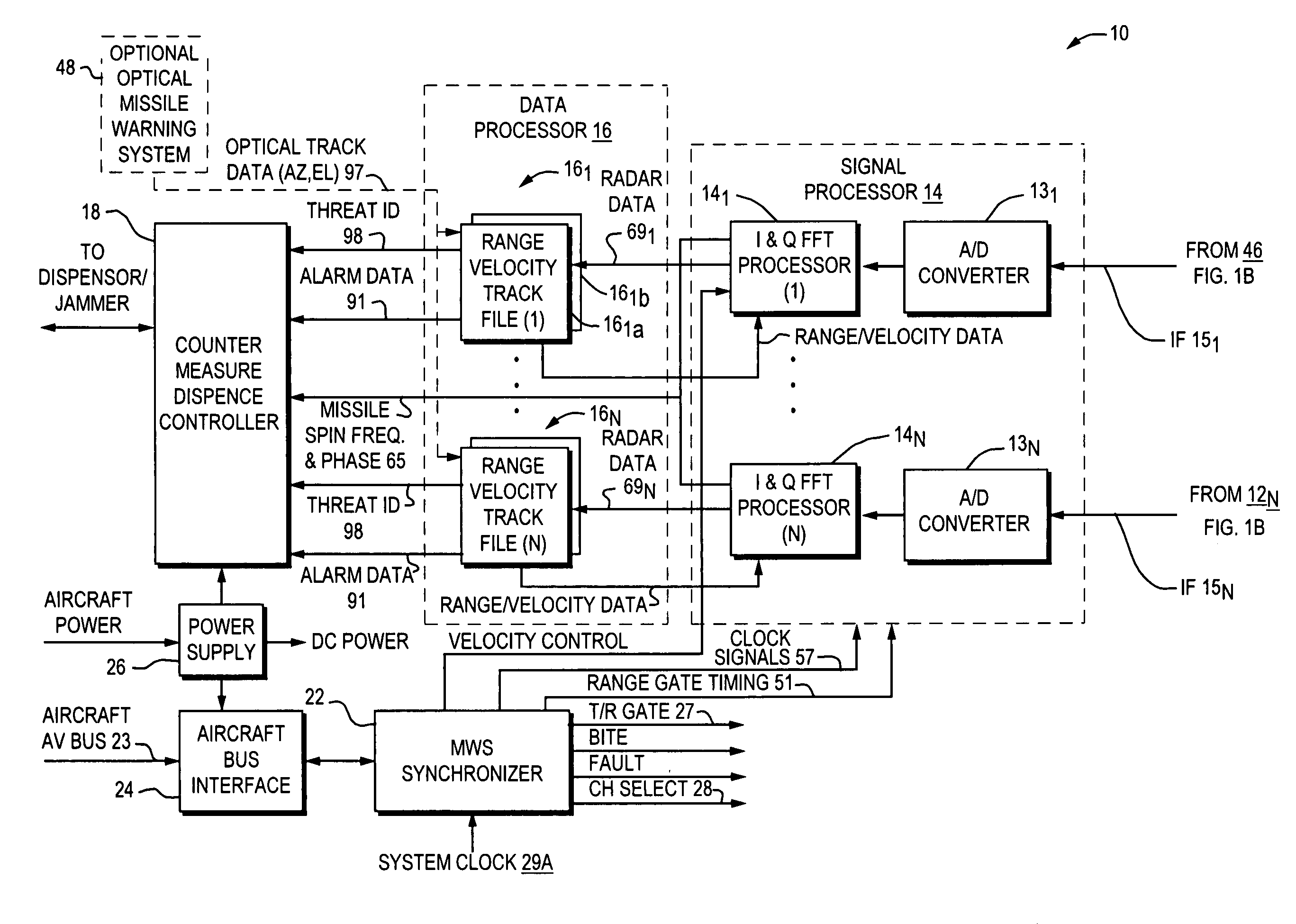
[0010]Accordingly, it is therefore an object of this invention to provide a distributed pulse Doppler missile warning system having two to six transmit / receive modules and antennas coupled to parallel processing channels to minimize losses and enhance detection range, and to promote faster response time at a minimum cost to the user.
[0012]It is a further object of this invention to provide the means to combine data from this pulse doppler missile warning system with data from an optical missile warning system. The combination allows the user to develop a three dimensional track of a missile with azimuth and elevation angles provided by the optical MWS of either an IR or UV type, and with range, velocity and acceleration provided by this pulse doppler radar. Since the false alarm sources for the optical and radar systems are uncorrelated, and the combined data produces a 3 dimensional track, this combination provides an even more rigorous validation and thus an ultra low false alarm rate.

Problems solved by technology

Limitations of this conventional architecture include lost duty factor and increased scan time for a specific antenna resulting from the need to sequentially service all antennas, compromises in the selection of pre and post detection integration times, and the necessity to run heavy, stiff and expensive low loss RF Cable to each antenna, a problem exacerbated on large aircraft.
In addition, these systems did not contain high speed data processors to insure that a low false alarm rate could be maintained in operational environments.
Acquisition mode was performed on all four antennas simultaneously, but critical bearing analysis required a reconfiguration of the parallel channels of the receiver resulting in a faster system, but not fully parallel and not instantaneous in its coverage.
Also, the parallel channels contain a significant amount of redundant, and low reliability, analog circuitry.
The disadvantage of this approach is that there is redundant hardware in the suite of equipments which are making the same measurements of the threat environment.
Clearly Mr. Tran's approach is not an optimum design configuration either in terms of acquisition, reliability, maintainability, logistical programming or training.

Method used


Image

  • Airborne distributed pulse doppler radar missile warning system
  • Airborne distributed pulse doppler radar missile warning system
  • Airborne distributed pulse doppler radar missile warning system

Examples


Embodiment Construction

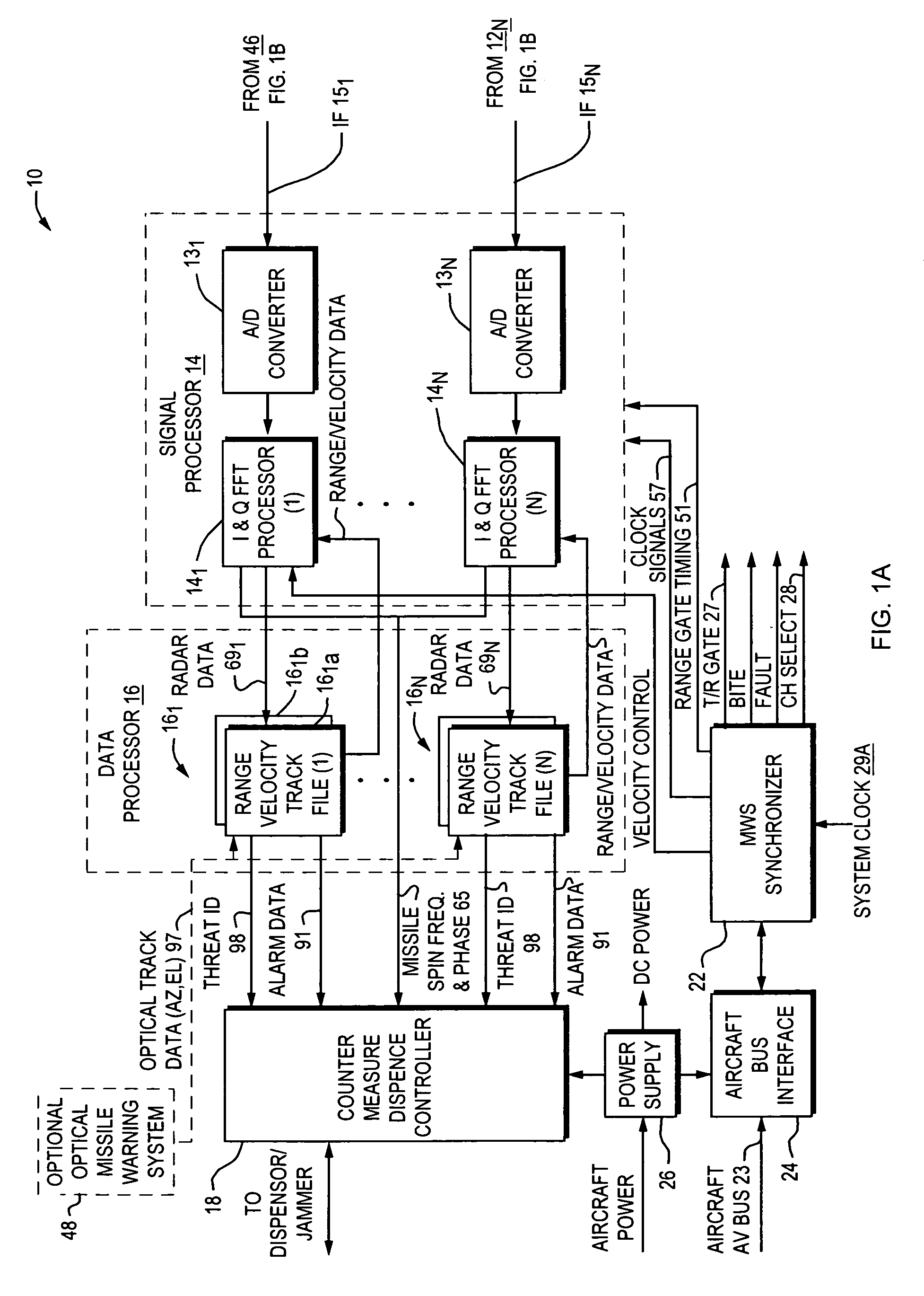
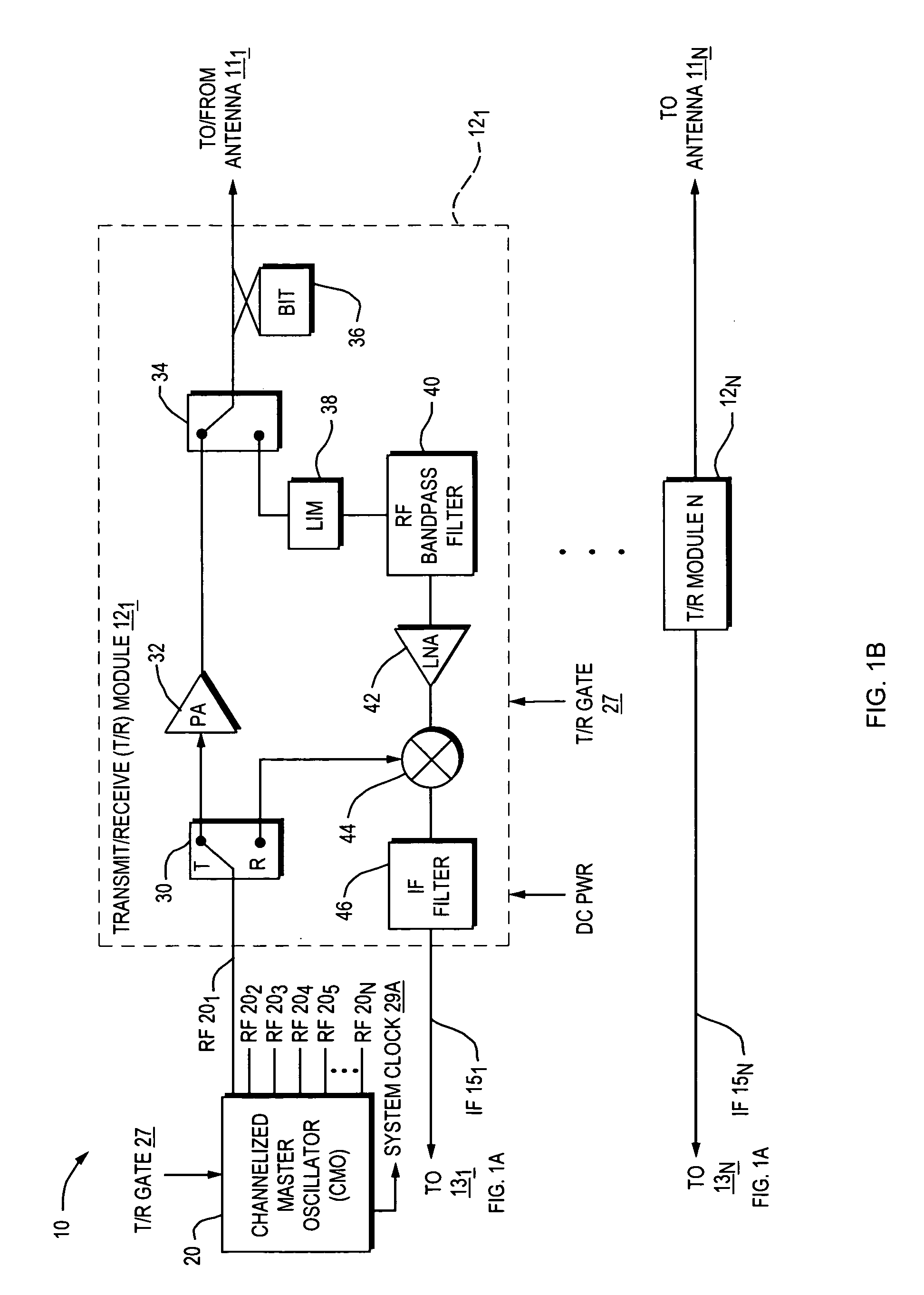
[0023]Referring to FIG. 1A and FIG. 1B, a block diagram is shown of a distributed pulse doppler missile warning system (DPDMWS) 10 according to the present invention. The DPDMWS 10 comprises a plurality of transmit / receive (T / R) modules 121-12N each connected to one of a plurality of antennas 111-11N. A channelized master oscillator (CMO) 20 provides a system clock 29a and RF signals 201-20N for each T / R module 121-12N. During transmit, the RF signals 201-20N are the same transmitted carrier frequency, and all transmissions occur at the same time. During receive, the CMO offsets the RF signal by the IF. An analog IF signal 151-15N from each T / R module 121-12N is connected to a signal processor 14 and the signal processor 14 comprises a plurality of analog to digital (A / D) converters 131-13N each one connected to one of a plurality of I&Q FFT Processors 141-14N i.e. one for receiving each T / R module IF output signal 151-15N. The A / D converters 131-13N are high speed with greater than...


PUM


Abstract

A digital missile warning system comprising a distributed pulse doppler radar having a plurality of antennas, each being coupled to a transmit / receive (T / R) module located adjacent to the antenna, and parallel signal processing channels including an A / D converter, FFT processor and a range / velocity track file processor in each channel for each antenna resulting in enhanced detection range, reduced False Alarm Rate (FAR), faster response time, reduced size, weight and installation requirements, improved reliability and reduced acquisition and life cycle costs. An optional optical missile warning system can provide azimuth and elevation data to the track file processors which enables a three (3) dimensional track of a missile, with azimuth and elevation angles provided by the optical system and range, velocity and acceleration data provided by the pulse doppler radar. The combination of Pulse Doppler Radar MWS and the Optical MWS produces close to a zero False Alarm Rate (FAR). Further, means to extract a threat IR missiles' roll rate and its seeker spin rate and phase angle are provided.

Description

BACKGROUND OF THE INVENTION[0001]1. Field of the Invention[0002]This invention relates generally to an Airborne Pulse Doppler Radar Missile Warning System and, in particular, to a distributed missile warning system having typically two to six antennas operating simultaneously and continuously with parallel transmit / receive modules, and parallel processing of the radar data to provide rapid detection and timely activation of counter-measures.[0003]2. Description of Related Art[0004]Conventional Airborne Pulse Doppler Radar Missile Warning Systems (MWS) use multiple, electrically small antennas to cover the required search volume. The antennas are electronically sequenced with a programmed dwell time. Centralized and common transmitter, receiver and signal processor elements are used to keep the costs affordable. The economic efficiency of this architecture made sense twenty-five years ago when these systems were developed and when the cost of these major components represented the ma...

Claims


Application Information

Patent Timeline
IPC IPC(8): G01S7/38
CPCG01S7/38F41H11/02
Inventor STEVENS, ROBERT R.
Owner STEVENS JR ROBERT R
Learn More