Multi primary conversion

a multi-primary conversion and conversion method technology, applied in the field of multi-primary conversion, can solve the problems of complex and delicate conversion process, freedom must be limited in a smart way, and achieve the effect of improving computational efficiency

Inactive Publication Date: 2012-01-05
TP VISION HLDG
View PDF7 Cites 13 Cited by
  • Summary
  • Abstract
  • Description
  • Claims
  • Application Information

AI Technical Summary

Benefits of technology

[0028]This approach further improves the computational efficiency by only considering the exemplary solutions that have the minimal and maximal amount of luminance concentrated in the first sub-pixel group. This simplification avoids the need to impose the balanced chrominance constraint in order to arrive at a unique well defined solution. By considering only the minimum and maximum luminance solutions, the entire procedure reduces to taking convex combinations thereof. The objective is to find the convex combination that approaches the desired luminance for the first sub-pixel group as closely as possible. This leads to an efficient multi-primary conversion algorithm that is able to account for balanced luminance constraints.

Problems solved by technology

This conversion, known as multi-primary conversion (further also referred to as MPC) is a delicate and complicated process.
This means that the freedom has to be limited in a smart way to optimize the behavior of the multi-primary display.
However, especially for multi-primary displays with more than 4 color primaries, a very high amount of processing power is required to implement the desired constraints.
This matching results in a loss of resolution if no constraints are imposed on the luminance distribution over the groups of sub-pixels.
However, the efficient specific approaches for 4 color primary multi-primary displays are not applicable to multi-primary displays with more than 4 color primaries.
On the other hand, a brute force approach to impose balanced luminance constraints will be very computationally intensive for more than 4 color primaries.

Method used


Image

  • Multi primary conversion
  • Multi primary conversion
  • Multi primary conversion

Examples


Embodiment Construction

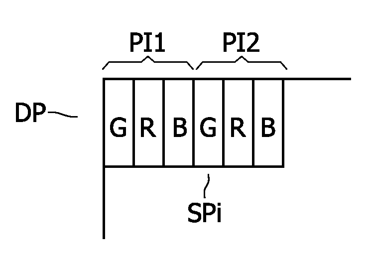
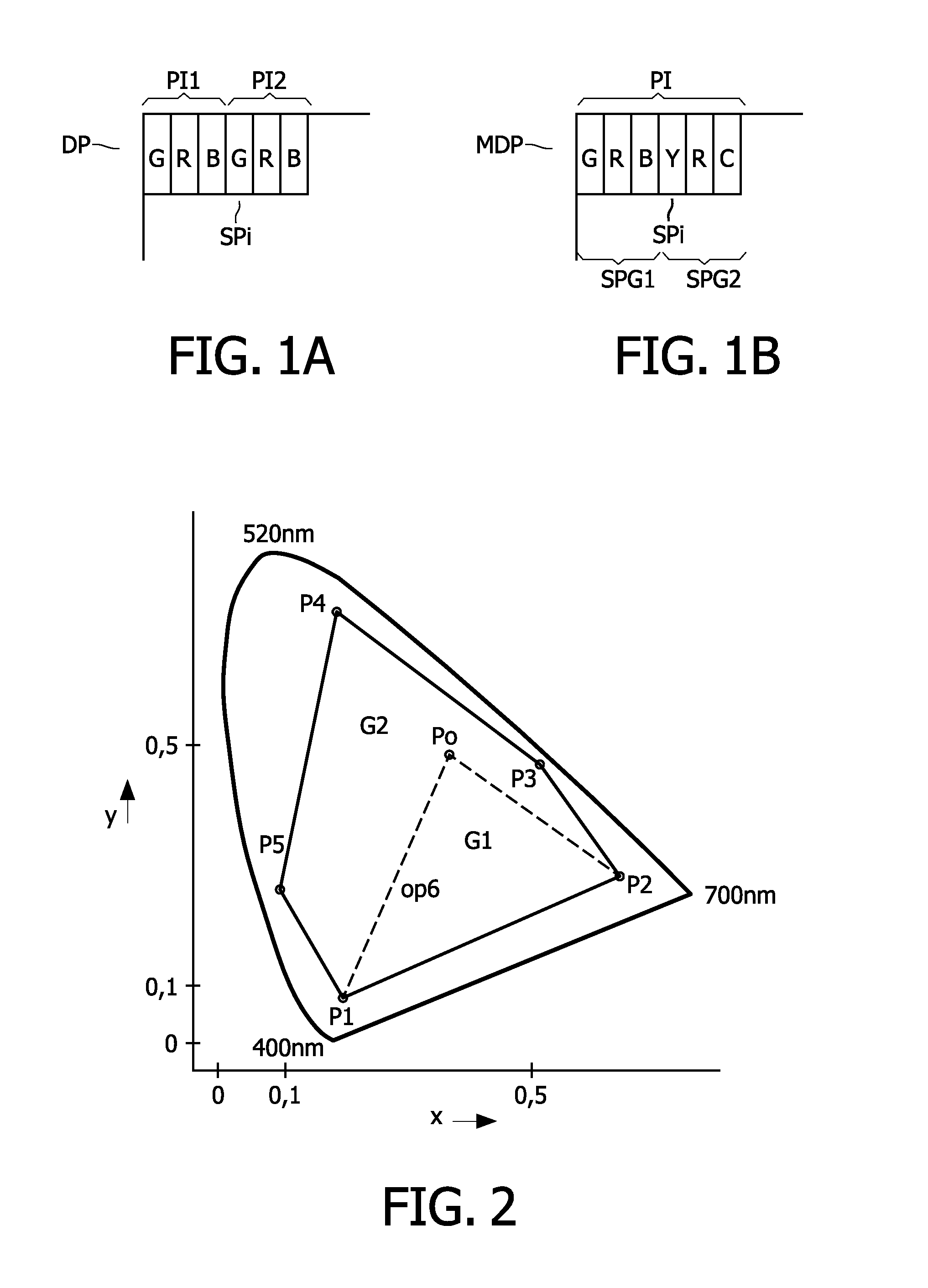
[0051]FIG. 1 schematically shows a pixel arrangement of a conventional RGB display and a multi-primary display with 6 color primaries. An actual display may have much more pixels than shown.

[0052]The RGB display DP has pixels PI1, PI2 each with three sub-pixels SPi which have the colors R (red), G (green), B (blue). The input signal which has to be displayed on the display DP has RGB or other components, such as for example YUV, which can easily be converted into RGB components. These RGB components define the drive values for the respective RGB sub-pixels. Because the number of sub-pixels per pixel is identical to the number of components of the input signal, the drive values can be deterministically found from the RGB components.

[0053]The multi-primary display MDP has pixels PI with 6 sub-pixels SPi which for example have the colors GRBYRC, wherein G is green, R is red, B is blue, Y is yellow, and C is cyan. In this example, the first group of sub-pixels SPG1 comprises the colors ...


PUM


Abstract

A multi-primary conversion (5) of input drive values (RGB) defines a color of a pixel (PI) of a multi-primary display(DP) in an M dimensional color space (XYZ) into N>M output drive values (di) in an N dimensional drive space. The N output drive values (di) drive N sub-pixels (SPi) of the pixel (PI). The color of the pixel (PI) in the color space (XYZ) is defined by linear combinations of N color primaries of the respective N sub-pixels (SPi). The multi-primary conversion(5) comprises: defining a constraint in the color space (XYZ) thereby causing in the color space (XYZ) a convex polytope (U0; L0; V50) defined by vertex points (V10, V11, V12; V20, V21; V50), wherein only colors in the color space (XYZ) belonging to the convex polytope fulfill the constraint, determining exemplary solutions of the output drive values (di) for at least a subset of the vertex points (V10, V11, V12; V20, V21; V50), and constructing the output drive values (di) fulfilling the constraint as a convex combination of the exemplary solutions.

Description

FIELD OF THE INVENTION[0001]The invention relates to a multi-primary conversion, a computer program product to perform the multi-primary conversion, a multi-primary converter, and a multi-primary display apparatus comprising the multi-primary converter.BACKGROUND OF THE INVENTION[0002]Conventional displays have pixels with 3 sub-pixels (also referred to as color pixels) per pixel. Usually, the pixel comprises a red, green and blue sub-pixel with color coordinates according the EBU norm. This selection of the colors of the sub-pixels allows an easy signal processing of the input signal which has or which can be converted into corresponding red, green and blue components for driving the respective colored sub-pixels. The color (luminance and chrominance) of a pixel is defined by the drive values of the sub-pixels. These drive values indicate a linear combination of the color primaries of the colors of the sub-pixels.[0003]Multi-primary displays use N>3 color primaries to represent ...

Claims


Application Information

Patent Timeline
Patent Type & Authority Applications(United States)
IPC IPC(8): G09G5/10
CPCH04N9/64
Inventor HINNEN, KAREL JOHANNES GERHARDUSHEKSTRA, GERBEN JOHANLANGENDIJK, ERNO HERMANUS ANTONIUSMUIJS, REMCO THEODORUS JOHANNESKLOMPENHOUWER, MICHIEL ADRIAASNZOON
Owner TP VISION HLDG
Why Eureka
Try Eureka