Optical beam splitter for use in an optoelectronic module, and a method for performing optical beam splitting in an optoelectronic module

a technology of optoelectronic modules and optical beam splitters, which is applied in the direction of optical elements, semiconductor lasers, instruments, etc., can solve the problems of reducing the optical output power level of the laser to a level, and it is generally not possible, or at least very difficult, to run a laser

Active Publication Date: 2012-01-05
AVAGO TECH INT SALES PTE LTD
View PDF1 Cites 55 Cited by
  • Summary
  • Abstract
  • Description
  • Claims
  • Application Information

AI Technical Summary

Benefits of technology

[0007]The invention is directed to an optical beam splitter for use in an optoelectronic module and a method for optically splitting a beam in an optoelectronic module. The optical beam splitter comprises a substrate having at least upper and lower surfaces that are parallel to one another, at least a first diffractive optical element formed on the lower surface of the substrate, and at least a first refractive optical element formed on the upper surface of the substrate. The first diffractive optical element receives a main beam of light produced by the light source and splits the main beam into at least first and second light portions L1 and L2, respectively. The first diffractive optical element tilts at least the first light portion L1 at a first preselected tilt angle relative to an imaginary line that is normal to the lower surface of the substrate and that extends between the lower and upper surfaces of the substrate. The first and second light portions L1 and L2 each have a particular percentage of the optical power of the main light beam. The second light portion L2 has a substantially larger percentage of the optical power of the main light beam than the first portion L1. The first refractive optical element receives the tilted first light portion L1 and directs the first light portion L1 onto a lens assembly of the optoelectronic module to optically couple the first light portion L1 into an end of an optical fiber coupled to the lens assembly. The optical power of the first light portion L1 that is directed onto the lens assembly is within a human eye safety limit.

Problems solved by technology

This symmetric, or even, split of the optical power can cause problems in some cases.
It is generally not possible, or at least very difficult, to run a laser at the high speed required for the optical communications link and simultaneously reduce the optical output power level of the laser to a level that is within eye safety limits.

Method used


Image

  • Optical beam splitter for use in an optoelectronic module, and a method for performing optical beam splitting in an optoelectronic module
  • Optical beam splitter for use in an optoelectronic module, and a method for performing optical beam splitting in an optoelectronic module
  • Optical beam splitter for use in an optoelectronic module, and a method for performing optical beam splitting in an optoelectronic module

Examples


Embodiment Construction

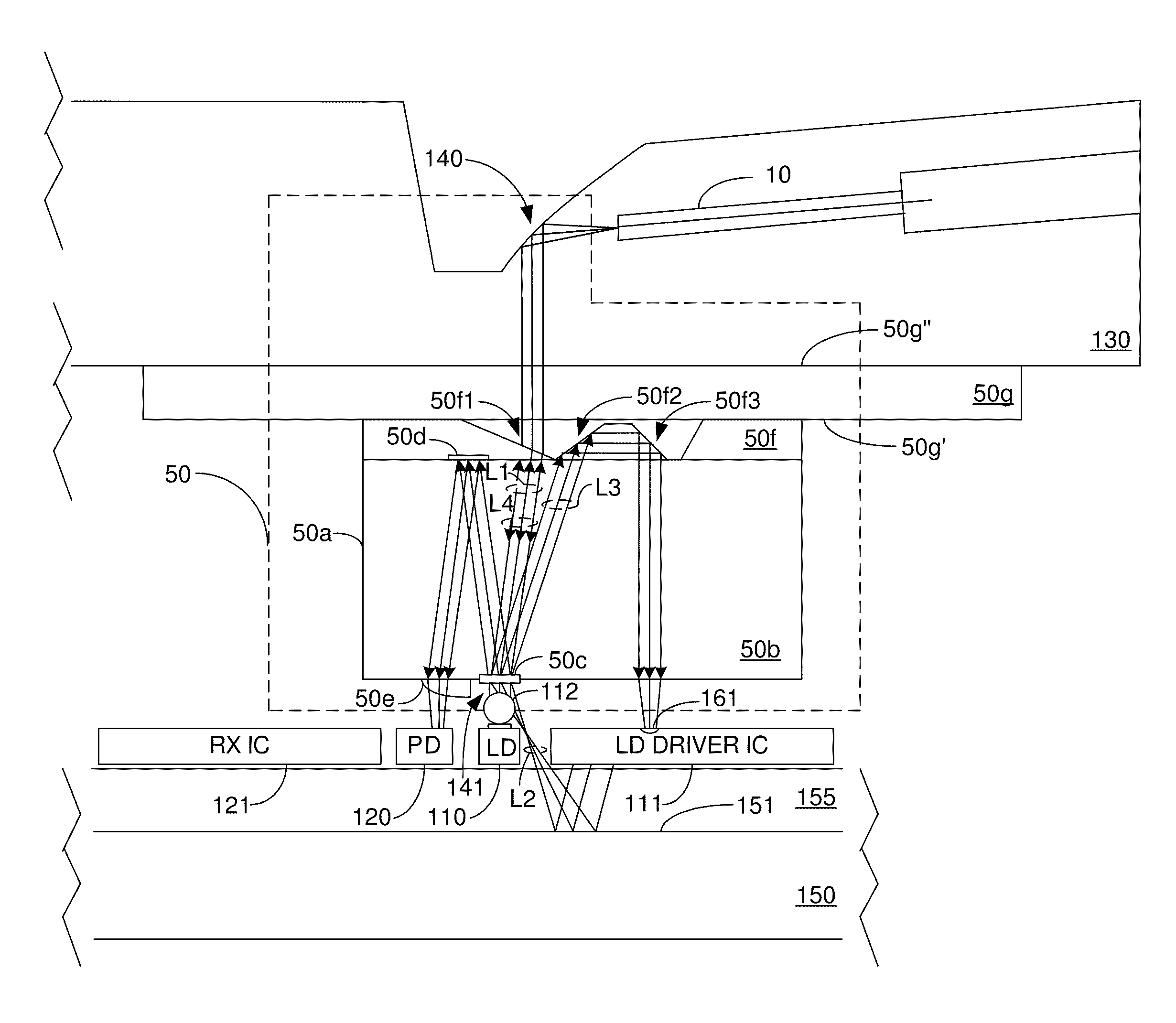
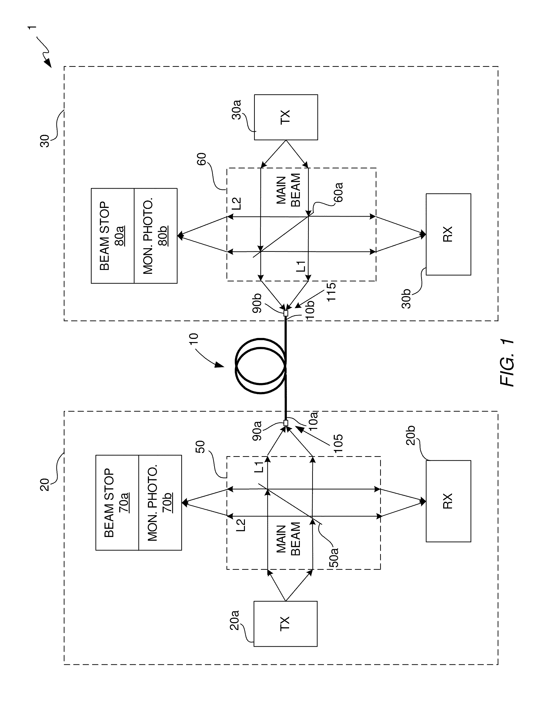
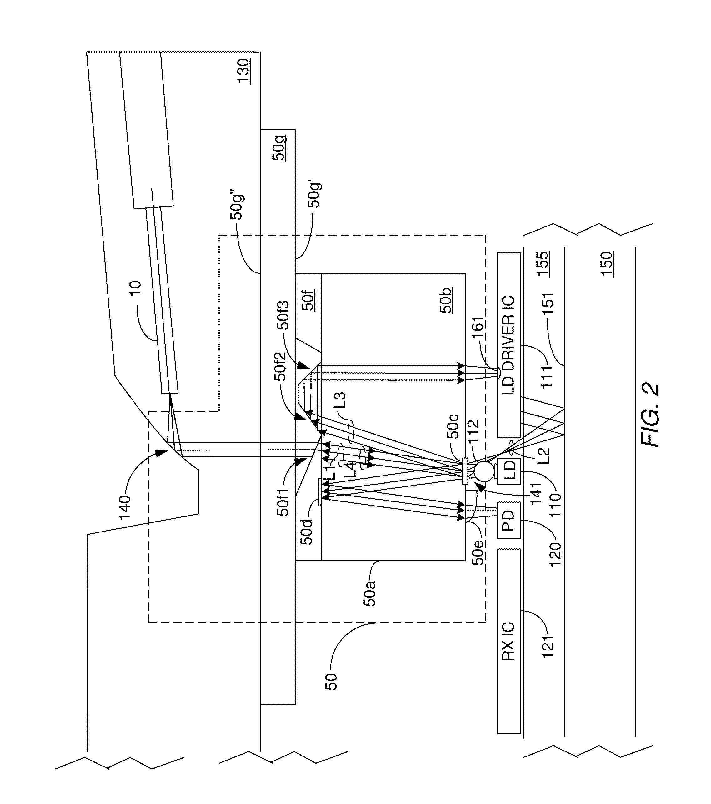
[0020]The invention is directed to an optical beam splitter for use in an optoelectronic module. The optical beam splitter is configured to split a main beam produced by a laser into at least first and second light portions that have different optical power levels. The first light portion, which is to be coupled into an end of a transmit optical fiber of an optical communications link, has an optical power level that is within eye safety limits and yet has sufficient optical power to avoid signal degradation problems. The first light portion has an optical power level that is less than the optical power level of the second light portion. The optoelectronic module in which the optical beam splitter is employed may be an optical transmitter module or an optical transceiver module. The optical communications link may be a unidirectional optical link or a bidirectional optical link. However, in order to demonstrate the various capabilities and advantages of the optical beam splitter, a ...


PUM

PropertyMeasurementUnit
tilt angleaaaaaaaaaa

Abstract

An optical beam splitter for use in an optoelectronic module and method are provided. The optical beam splitter is configured to split a main beam produced by a laser into at least first and second light portions that have different optical power levels. The first light portion, which is to be coupled into an end of a transmit optical fiber of an optical communications link, has an optical power level that is within eye safety limits and yet has sufficient optical power to avoid signal degradation problems. The optical power level of the first light portion is less than the optical power level of the second light portion. The optical beam splitter is capable of being implemented in a unidirectional or a bidirectional optical link.

Description

TECHNICAL FIELD OF THE INVENTION[0001]The invention relates to optoelectronic modules. More particularly, the invention relates to an optical beam splitter for use in an optoelectronic module for splitting a beam into at least two portions that have different levels of optical power.BACKGROUND OF THE INVENTION[0002]In optical communications networks, optoelectronic modules are used to transmit and / or receive optical signals over optical fibers. The optoelectronic module may be configured as an optical transmitter that transmits optical signals, an optical receiver that receives optical signals, or an optical transceiver that transmits and receives optical signals. On the transmit side of an optical transmitter or transceiver module, a light source (e.g., a laser diode) generates amplitude modulated optical signals that represent data, which are optically coupled by an optics system of the module into an end of a transmit optical fiber. The signals are then transmitted over the trans...

Claims


Application Information

Patent Timeline
Patent Type & Authority Applications(United States)
IPC IPC(8): G02B27/42
CPCG02B6/4206G02B6/4214G02B6/4246H01S5/005Y10T29/49899H01S5/02284H01S5/0683Y10T29/4987H01S5/02248H01S5/02325H01S5/02251G02B6/4204H01S5/0225
Inventor MCCOLLOCH, LAURENCE R.WEN, PENGYUE
Owner AVAGO TECH INT SALES PTE LTD
Why Eureka
Try Eureka