Electric Power Generating System with Boost Converter/Synchronous Active Filter

a technology of synchronous active filter and electric power generating system, which is applied in the direction of electric generator control, dynamo-electric converter control, emergency power supply arrangement, etc., and can solve problems such as increasing system nois

Active Publication Date: 2012-01-12
HAMILTON SUNDSTRAND CORP
View PDF10 Cites 34 Cited by
  • Summary
  • Abstract
  • Description
  • Claims
  • Application Information

AI Technical Summary

Problems solved by technology

Another approach to reduce DC bus voltage ripple includes increasing the frequency bandwidth of an active rectifier that rectifies the generator output; however, this approach may increase system noise.

Method used


Image

  • Electric Power Generating System with Boost Converter/Synchronous Active Filter
  • Electric Power Generating System with Boost Converter/Synchronous Active Filter
  • Electric Power Generating System with Boost Converter/Synchronous Active Filter

Examples


Embodiment Construction

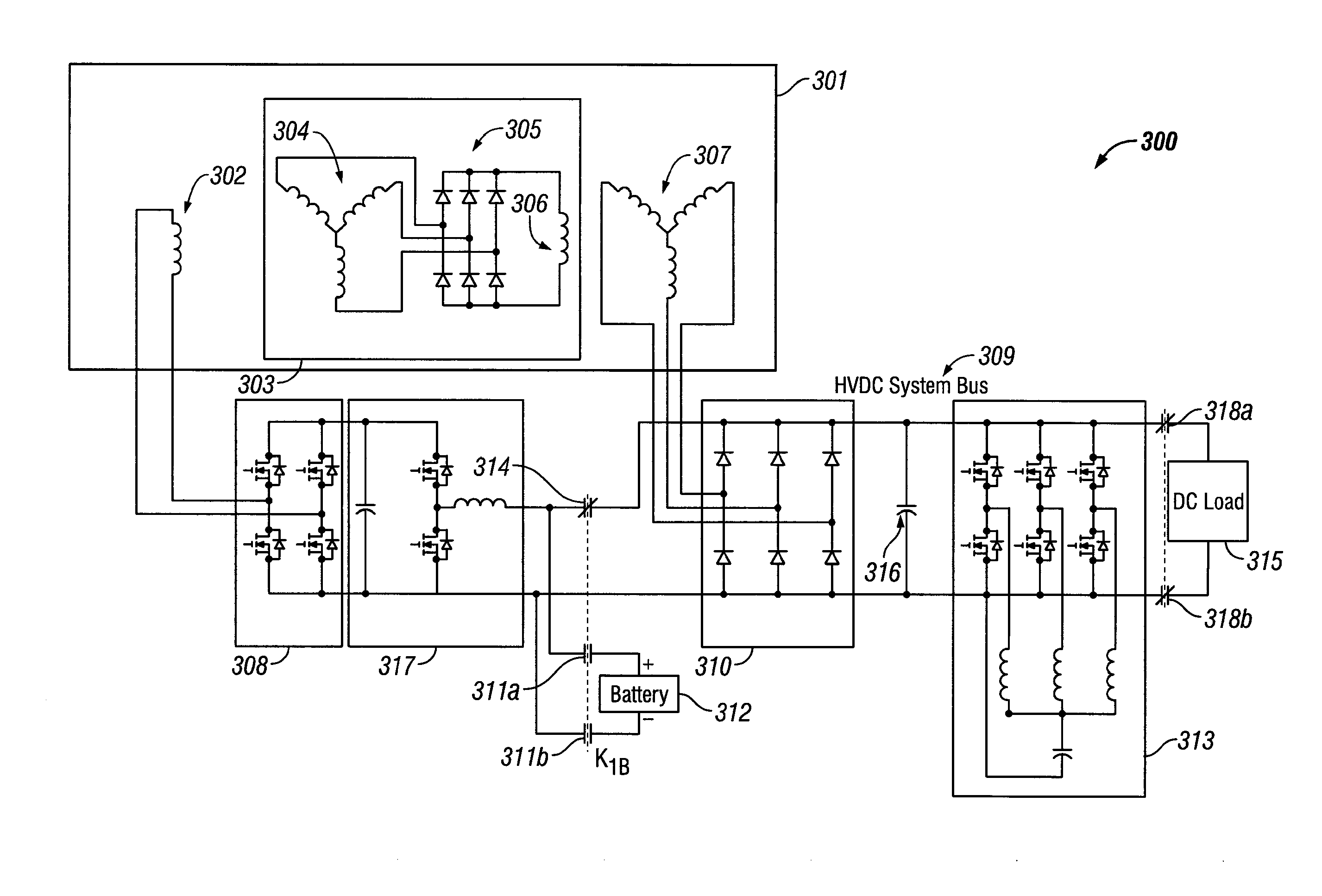
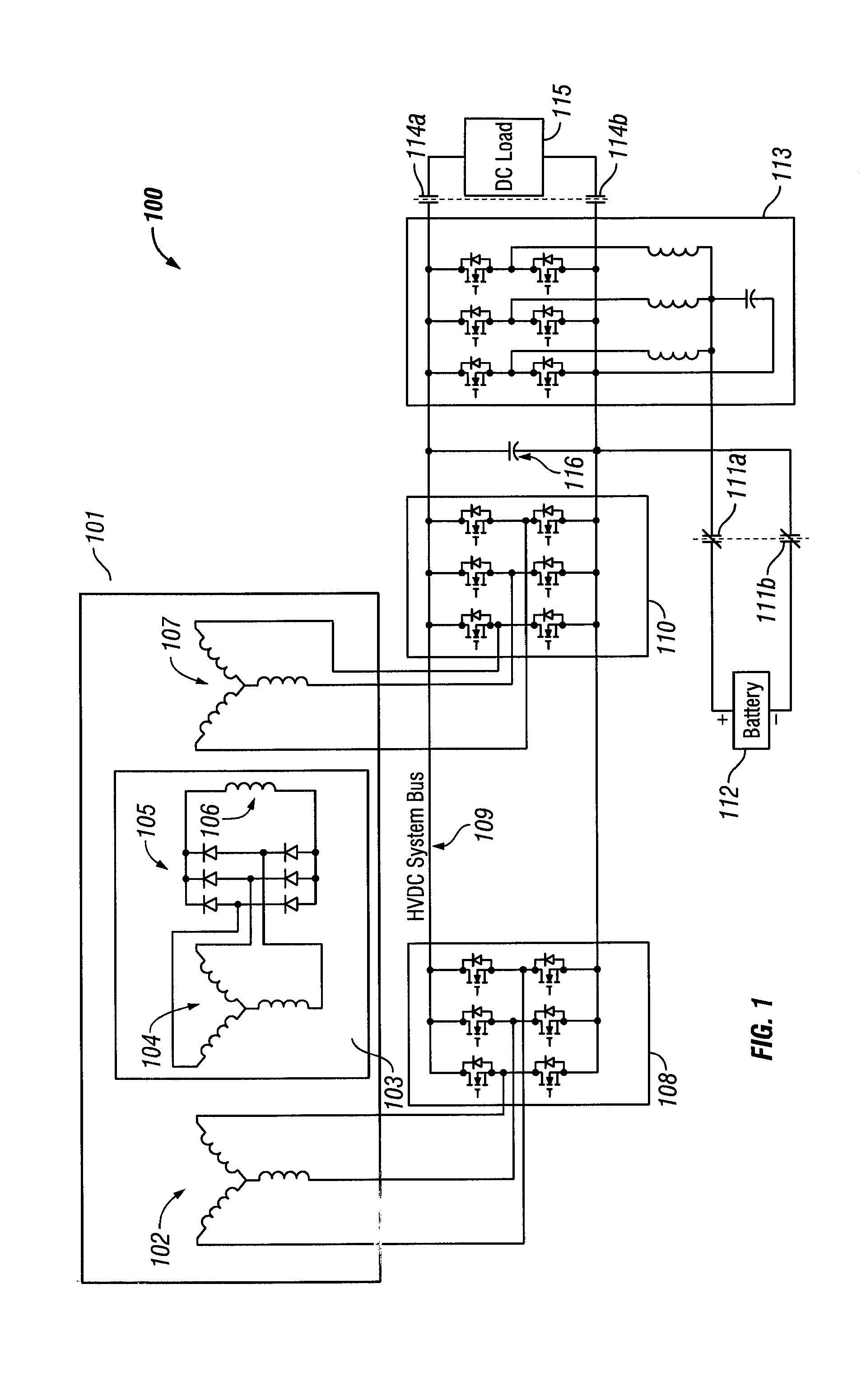
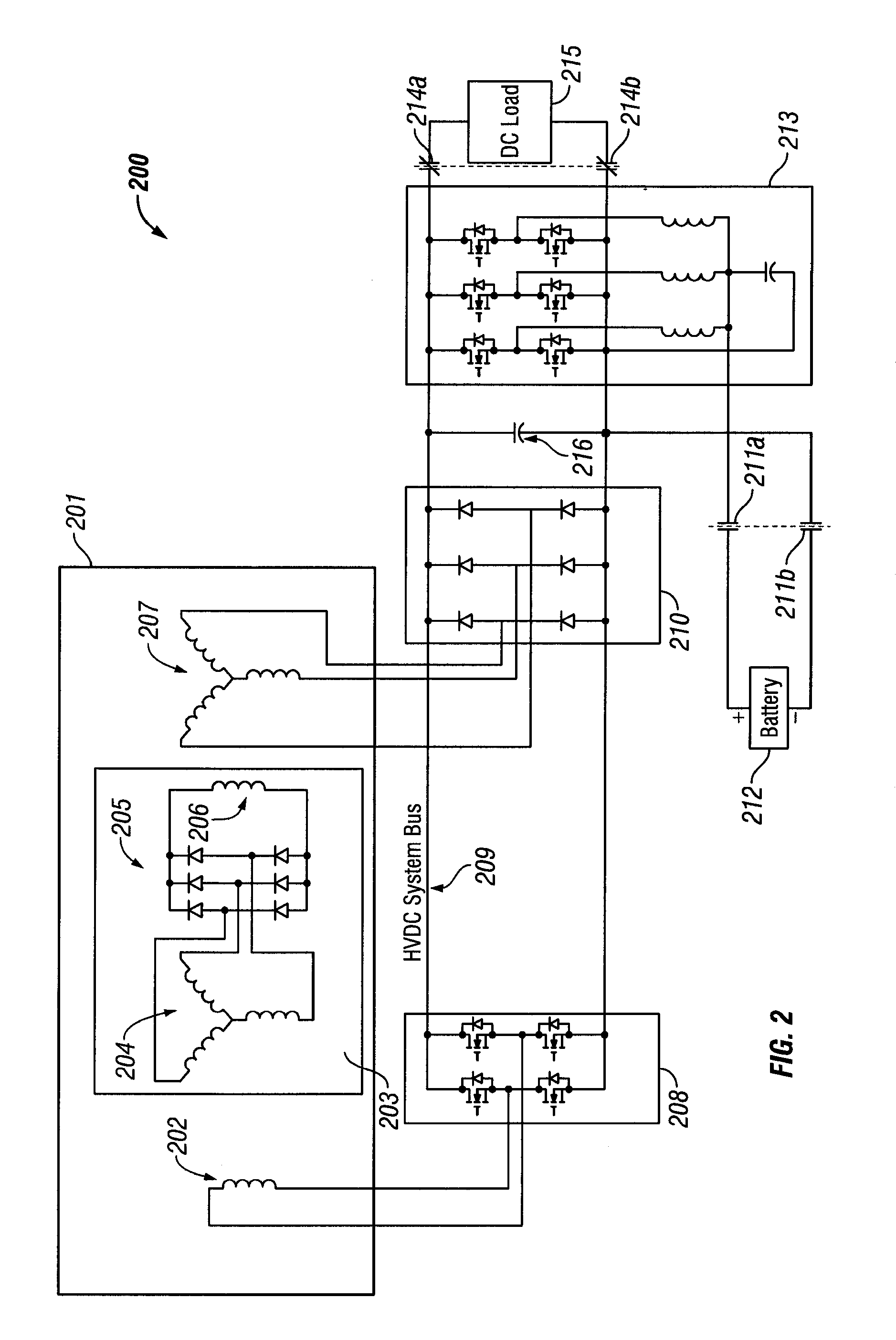
[0013]Embodiments of systems and methods for an EPGS with a boost converter and a synchronous active filter (SAF) are provided, with exemplary embodiments being discussed below in detail. A boost converter is a DC-DC power converter that has an output voltage that is greater than its input voltage. The boost converter may be connected to a battery that powers a generator via the boost converter and start inverter during startup. The generator is operated as a motor in the startup to convert electrical power supplied by a start inverter into motive power, which is provided to the prime mover to bring it up to self-sustaining speed. In the case of a WF generator, AC power is provided to the armature windings of the main portion of the WF generator and to AC exciter field windings, so that the motive power may be developed. This may be accomplished by using two separate inverters. During generate mode, the DC bus is connected to a DC load, and the power converter is reconfigured as an ...


PUM


Abstract

A method of startup of an electric start electrical power generating system (EPGS) is provided. The EPGS includes a generator configured to power a direct current (DC) load via a DC bus. The method includes: disconnecting the DC load from the DC bus; connecting a battery to a boost converter, the boost converter being connected to the generator; powering the generator using the battery via the boost converter; when the generator reaches a minimum speed: disconnecting the battery from the boost converter; deactivating the boost converter; and activating a synchronous active filter, the synchronous active filter being connected to the DC bus; bringing up a voltage on the DC bus by the generator; and when the voltage on the DC bus reaches a predetermined level, connecting the DC load to the DC bus.

Description

FIELD OF INVENTION[0001]The subject matter disclosed herein relates generally to the field of electrical power generating systems.DESCRIPTION OF RELATED ART[0002]Vehicles, such as military hybrid vehicles or aircraft, may include electric power generating systems (EPGS) that utilize a synchronous generator to power a DC load in the vehicle. The synchronous generator may comprise a permanent magnet (PM) or wound field (WF) generator. A voltage ripple on the direct current (DC) bus exists after rectification of the generator output. To reduce the DC bus voltage ripple to levels that are appropriate to meet specification requirements for the DC load, a relatively large DC bus capacitor may be required in the EPGS, adding weight and size to the EPGS. The DC bus capacitor is sized based on the ripple frequency, and may need to be significantly increased when the generator operates at a relatively low speed. Another approach to reduce DC bus voltage ripple includes increasing the frequenc...

Claims


Application Information

Patent Timeline
Patent Type & Authority Applications(United States)
IPC IPC(8): H02J1/00
CPCH02J3/36H02M1/36H02M5/293H02M1/15H02P2101/30H02M3/1584H02P1/52H02P9/302H02M3/1582
Inventor ROZMAN, GREGORY I.MOSS, STEVEN J.
Owner HAMILTON SUNDSTRAND CORP
Why Eureka
Try Eureka