Post-ash sidewall healing

a sidewall and ash technology, applied in the field of post-ash sidewall healing, can solve the problem that the etching process may be easily timed, and achieve the effect of convenient timed

Inactive Publication Date: 2012-01-12
APPLIED MATERIALS INC
View PDF8 Cites 227 Cited by
  • Summary
  • Abstract
  • Description
  • Claims
  • Application Information

AI Technical Summary

Benefits of technology

[0006]Methods of decreasing the effective dielectric constant present between two conducting components of an integrated circuit are described. The methods involve the use of a gas phase etch which is selective towards the oxygen-rich portion of the low-K dielectr

Problems solved by technology

The etch process may be easily timed since the gas phase etch

Method used


Image

  • Post-ash sidewall healing
  • Post-ash sidewall healing
  • Post-ash sidewall healing

Examples


Embodiment Construction

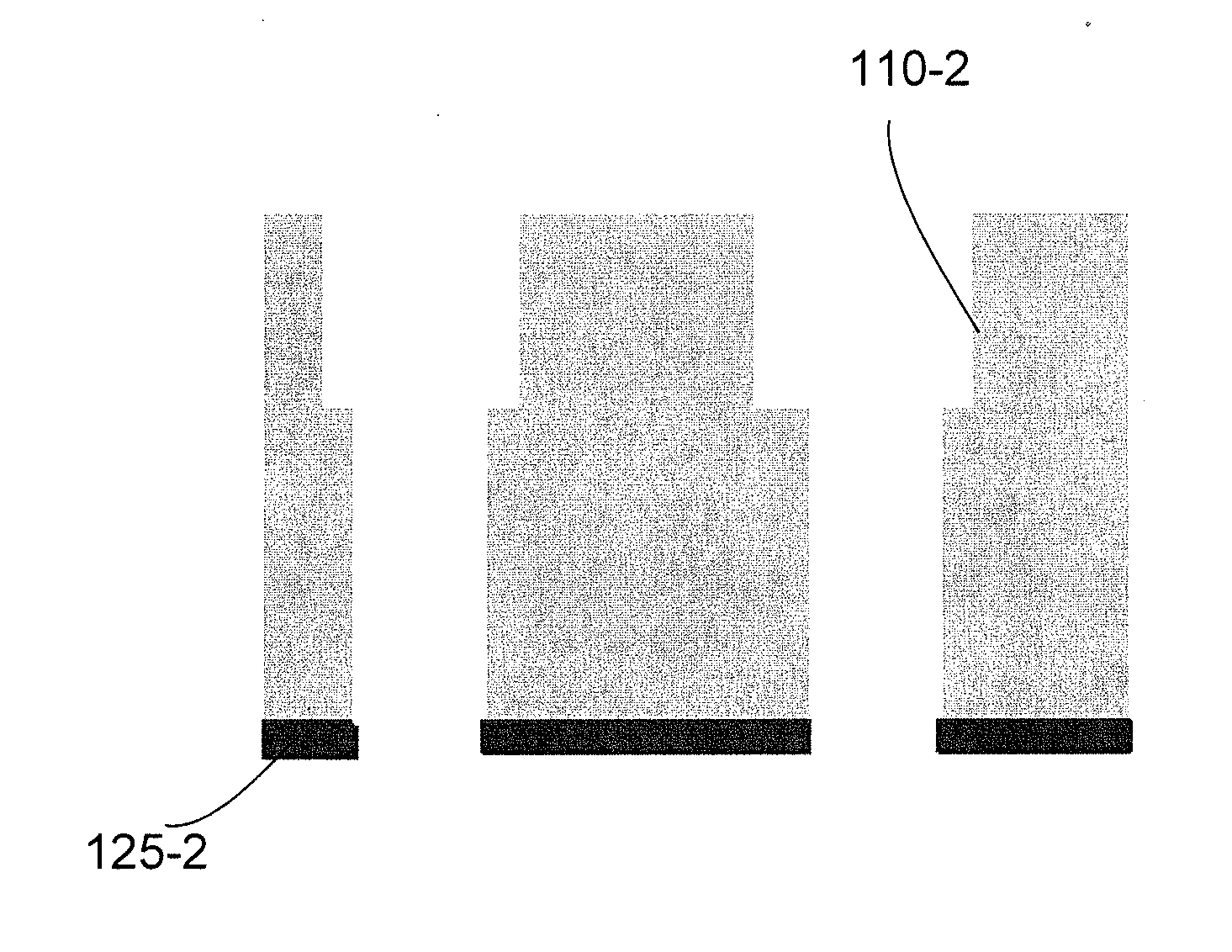
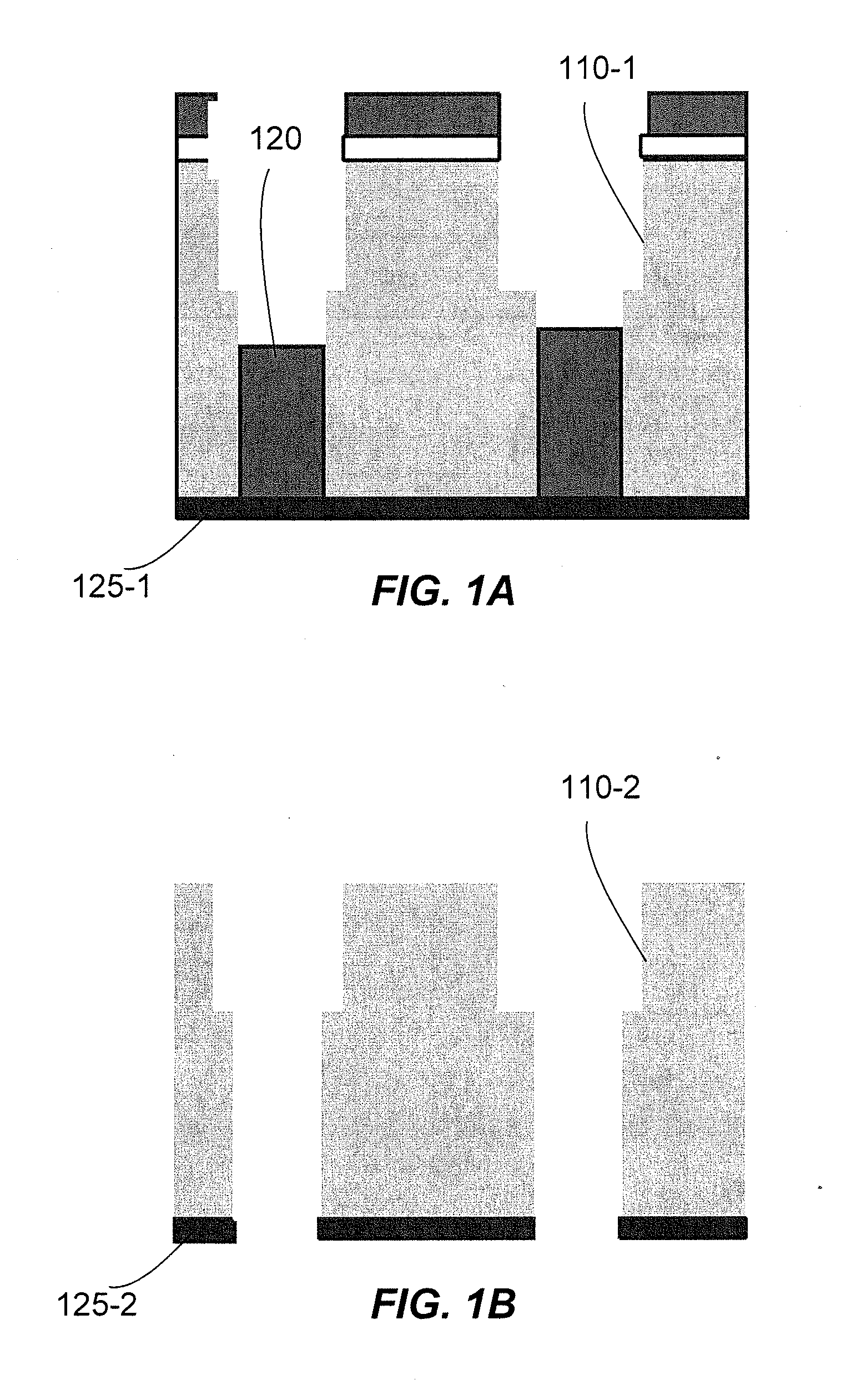
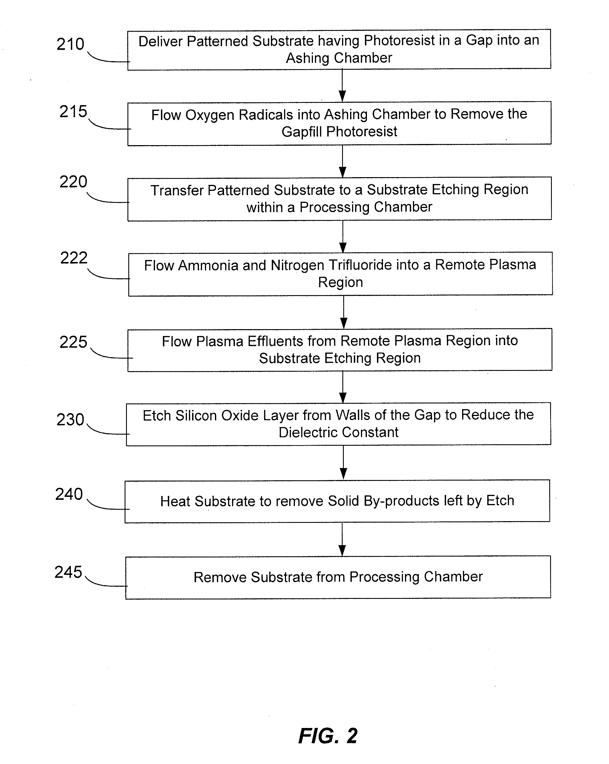
[0015]Methods of decreasing the effective dielectric constant present between two conducting components of an integrated circuit are described. The methods involve the use of a gas phase etch which is selective towards the oxygen-rich portion of the low-K dielectric layer. The etch rate attenuates as the etch process passes through the relatively high-K oxygen-rich portion and reaches the low-K portion. The etch process may be easily timed since the gas phase etch process does not readily remove the desirable low-K portion. Gas phase etches are preferable to liquid buffered oxide etches especially for processing patterned substrates. Gas phase etchants are more easily removed from confined structures than liquid etchants.

[0016]Embodiments of the invention are directed to methods of etching a low-K material on a patterned substrate to increase the effective dielectric constant thereby improving device performance. An exemplary process flow which benefits from methods presented herein...


PUM


Abstract

Methods of decreasing the effective dielectric constant present between two conducting components of an integrated circuit are described. The methods involve the use of a gas phase etch which is selective towards the oxygen-rich portion of the low-K dielectric layer. The etch rate attenuates as the etch process passes through the relatively high-K oxygen-rich portion and reaches the low-K portion. The etch process may be easily timed since the gas phase etch process does not readily remove the desirable low-K portion.

Description

CROSS-REFERENCES TO RELATED APPLICATIONS[0001]This application claims the benefit of U.S. Prov. Pat. App. No. 61 / 362,776 filed Jul. 9, 2010, and titled “POST-ASH SIDEWALL HEALING,” which is incorporated herein by reference in its entirety for all purposes.BACKGROUND OF THE INVENTION[0002]Integrated circuit fabrication methods have reached a point where many hundreds of millions of transistors are routinely formed on a single chip. Each new generation of fabrication techniques and equipment are allowing commercial scale fabrication of ever smaller and faster transistors, but also increase the difficulty to make even smaller, faster circuit elements. The shrinking dimensions of circuit elements, now well below the 50 nm threshold, has caused chip designers to look for new low-resistivity conductive materials and new low-dielectric constant (i.e., low-k) insulating materials to improve (or simply maintain) the electrical performance of the integrated circuit.[0003]Parasitic capacitance...

Claims


Application Information

Patent Timeline
IPC IPC(8): H01L21/3065
CPCH01L21/3105H01L21/76814H01L21/31138H01L21/31116
Inventor CUI, ZHENJIANGWANG, ANCHUANNAIK, MEHULINGLE, NITINLEE, YOUNGVENKATARAMAN, SHANKAR
Owner APPLIED MATERIALS INC
Why Eureka
Try Eureka