Method and system for long range wireless power transfer

a wireless power transfer and wireless technology, applied in the field of long-range wireless power transfer, can solve the problem that the system is incapable of efficient power transfer with respect to relatively long-range applications, and achieve the effect of high power transfer efficiency

Active Publication Date: 2012-01-12
MARYLAND UNIV OF
View PDF2 Cites 59 Cited by
  • Summary
  • Abstract
  • Description
  • Claims
  • Application Information

AI Technical Summary

Benefits of technology

[0014]It is therefore an object of the present invention to provide a long range wireless power transfer system where high efficiencies of power transfer are attained due to a reduction in or elimination of parasitic loss mechanisms attributed to the internal material dissipation (resistive, or ohmic, losses) as well as radiative losses.
[0015]It is a further object of the present invention to provide a long range inductive power transfer system in which the oscillators are manufactured, based on superconducting principles (superconducting materials, as well as compactness for cryo-cooling) to reduce the ohmic losses.
[0016]It is another object of the present invention to provide an efficient long range wireless power transfer system in which the system components are free of dielectric losses.

Problems solved by technology

However, this type of system is incapable of efficient power transfer with respect to relatively long range applications.

Method used


Image

  • Method and system for long range wireless power transfer
  • Method and system for long range wireless power transfer
  • Method and system for long range wireless power transfer

Examples


Embodiment Construction

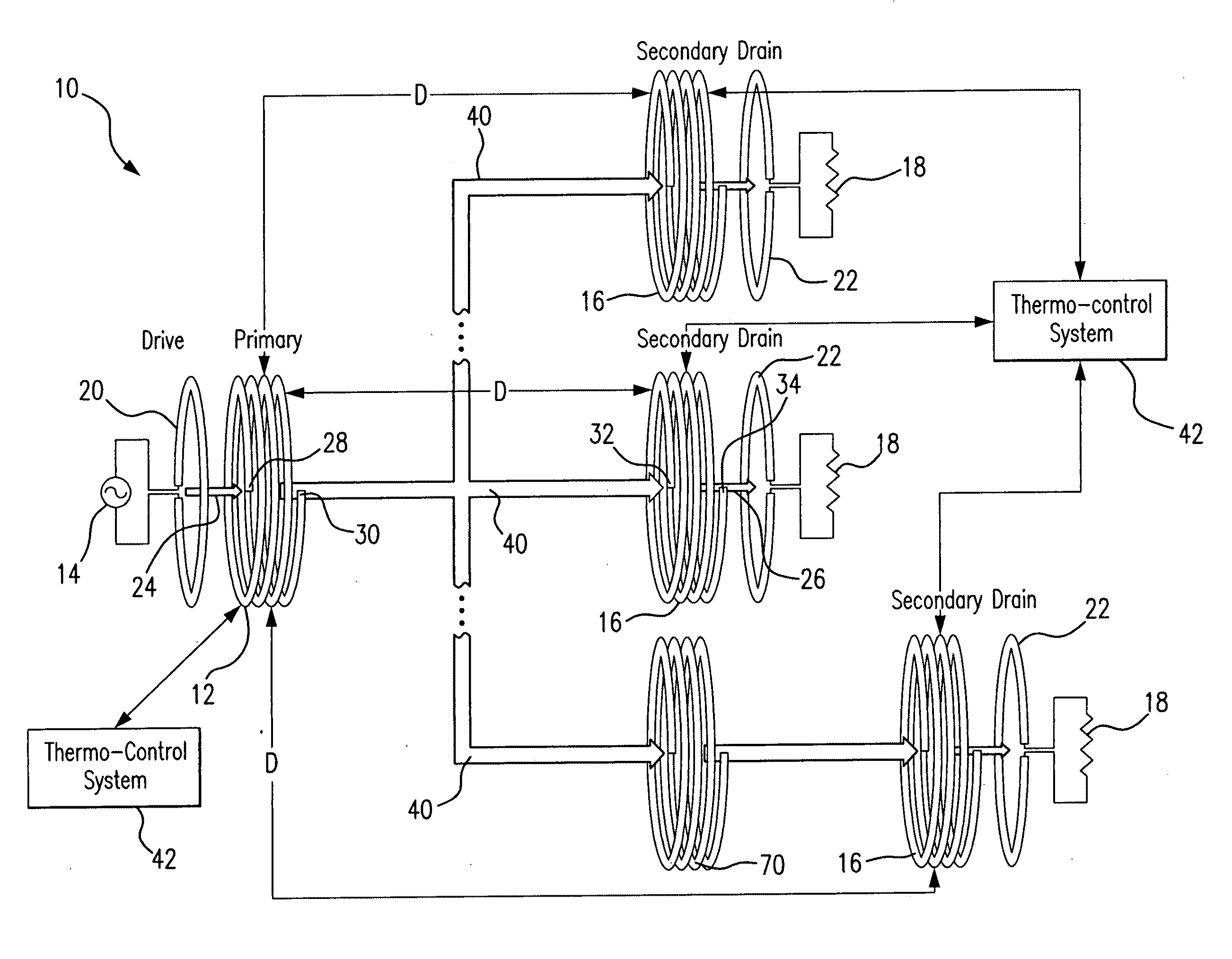
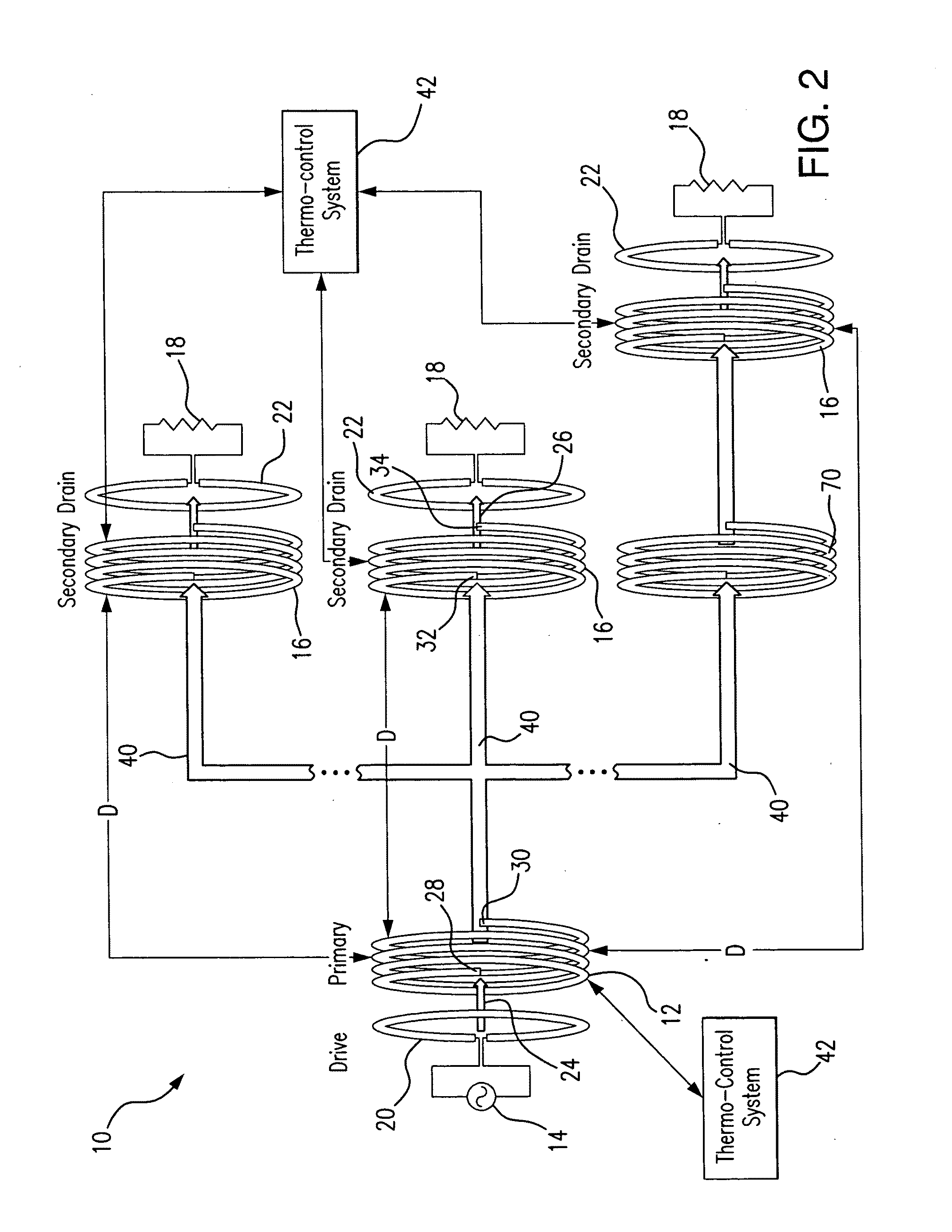
[0050]Referring to FIGS. 2 and 3, the system 10 for a long range inductive power transfer includes a source oscillator 12 (also referred to herein as a transmitting oscillator, or a primary oscillator) which is connected to a power source 14, and one or several receiving (also referred to herein as secondary) oscillator(s) 16 physically separated by a distance D from the source oscillator 12.

[0051]As presented in FIG. 2, the system 10 may include a number of receiving oscillators 16, each for powering a corresponding power consuming device 18, such as, for example, cell phones, TVs, computers, etc. It is to be understood by those skilled in the art, that although any number of the secondary oscillators 16 is envisioned in the present system, for the sake of simplicity further disclosure will be presented based on a single secondary oscillator design.

[0052]The energy provided by the power source 14 to the source oscillator 12 is wirelessly transferred in the system 10 in a non-radiat...


PUM

PropertyMeasurementUnit
frequencyaaaaaaaaaa
distanceaaaaaaaaaa
diametersaaaaaaaaaa

Abstract

A wireless energy transfer system includes a primary and one (or more) secondary oscillators for transferring energy therebetween when resonating at the same frequency. The long range (up to and beyond 100 m) efficient (as high as and above 50%) energy transfer is achieved due to minimizing (or eliminating) losses in the system. Superconducting materials are used for all current carrying elements, dielectrics are either avoided altogether, or those are used with a low dissipation factor, and the system is operated at reduced frequencies (below 1 MHz). The oscillators are contoured as a compact flat coil formed from a superconducting wire material. The energy wavelengths exceed the coils diameter by several orders of magnitude. The reduction in radiative losses is enhanced by adding external dielectric-less electrical capacitance to each oscillator coil to reduce the operating frequency. The dielectric strength of the capacitor is increased by applying a magnetic cross-field to the capacitor to impede the electrons motion across an air gap defined between coaxial cylindrical electrodes.

Description

REFERENCE TO THE RELATED APPLICATION[0001]This utility patent application is based on the Provisional Patent Application No. 61 / 350,229 filed 1 Jun. 2010.FIELD OF THE INVENTION[0002]The present invention is directed to power transfer systems, and more in particular to a system for wireless energy transfer between electromagnetic resonant objects.[0003]More in particular, the present invention is directed to the power transfer between resonators (also referred to herein intermittently as oscillators) in highly efficient and low loss manner, thereby permitting long range wireless power transfer.[0004]The present invention is further directed to a system for wireless power transfer with diminished resistive, dielectric, and radiative losses, where such is operated at reduced frequencies to produce higher efficiencies at long range distances.[0005]The present invention also is directed to a system for wireless power transfer between electromagnetic oscillators spaced apart at a desired ...

Claims


Application Information

Patent Timeline
Patent Type & Authority Applications(United States)
IPC IPC(8): H01L39/02H01L39/12H01F38/14
CPCH03B15/003H02J17/00H02J50/12H02J50/50H02J50/70
Inventor SEDWICK, RAYMOND J.
Owner MARYLAND UNIV OF
Why Eureka
Try Eureka