Heat exchanger and method of manufacturing the same

a technology of heat exchanger and heat exchanger, which is applied in the direction of lighting and heating apparatus, semiconductor/solid-state device details, laminated elements, etc., to achieve the effects of increasing heat, increasing rigidity and strength in the structure, and increasing cooling performan

Inactive Publication Date: 2012-01-19
TOYOTA JIDOSHA KK
View PDF10 Cites 53 Cited by
  • Summary
  • Abstract
  • Description
  • Claims
  • Application Information

AI Technical Summary

Benefits of technology

[0024]According to the above configuration (1), there is no need to consider durability of the jig during manufacturing and therefore rigidity and strength in the structure can be enhanced by the pins left between the fin portions. Further, the coolant is caused to flow through the space between the fin portions, so that the coolant is prompted to form a turbulent flow, thereby increasing an amount of heat to be dissipated from each fin portion into the coolant. Thus, the cooling performance can be increased.
[0025]According to the above configuration (2), in addition to the advantages of the above configuration (1), the turbulent flow of coolant flowing through the spaces is made turbulent repeatedly and hence a turbulent flow can be further induced. This makes it possible to further improve the cooling performance.
[0026]According to the above configuration (3), in addition to the advantages of the above configuration (1) or (2), the pins can be easily press-fitted into the spaces between the fin portions.
[0027]According to the above configuration (4), in addition to the advantages of the above configuration (1) or (2), there is no need to apply a larger axial force than is necessary to the screws for the purpose of press-fitting the screws into the space(s) between the fin portions. It is therefore possible to prevent the screws from dropping out from the space(s) between the fin portions.
[0028]According to the above configuration (5), there is no need to consider durability of the jig during manufacturing and therefore rigidity and strength in the structure can be enhanced by the pins left between the fin portions. Further, the coolant is caused to flow through the space between the fin portions, so that the coolant is prompted to form a turbulent flow, thereby increasing an amount of heat to be dissipated from each fin portion into the coolant. Thus, the cooling performance can be increased.
[0029]According to the above configuration (6), in addition to the advantages of the above configuration (5), the turbulent flow of coolant flowing through the spaces is made turbulent repeatedly and hence a turbulent flow can be further induced. This makes it possible to further improve the cooling performance.

Problems solved by technology

Secondly, the edge portions of the fin portions made in straight shapes by extrusion are bent by a jig (pins) in a direction perpendicular to the extruding direction.

Method used


Image

  • Heat exchanger and method of manufacturing the same
  • Heat exchanger and method of manufacturing the same
  • Heat exchanger and method of manufacturing the same

Examples


first embodiment

[0047]A detailed description of a first preferred embodiment of the present invention, embodying a heat exchanger and a manufacturing method thereof, will now be given referring to the accompanying drawings.

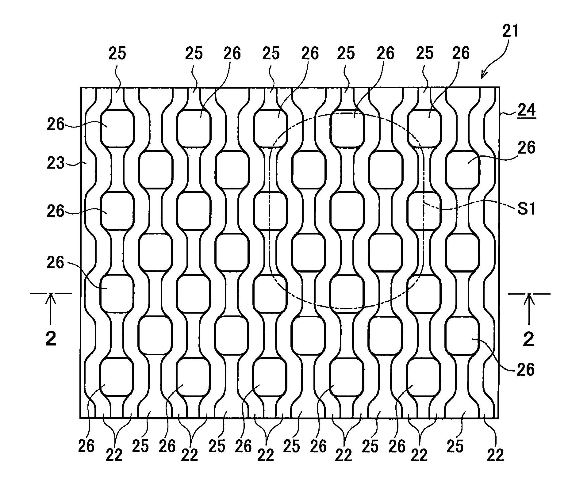
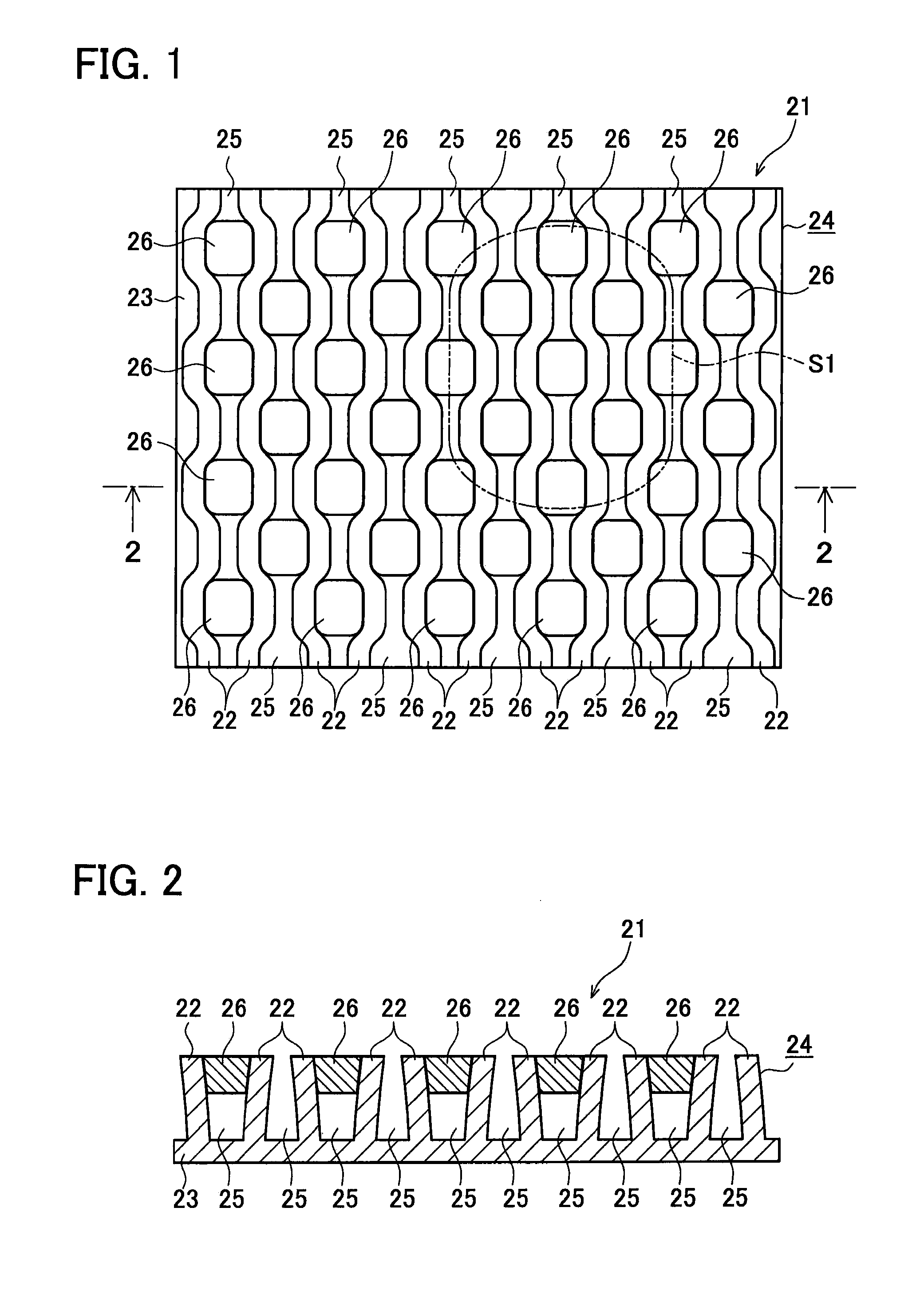
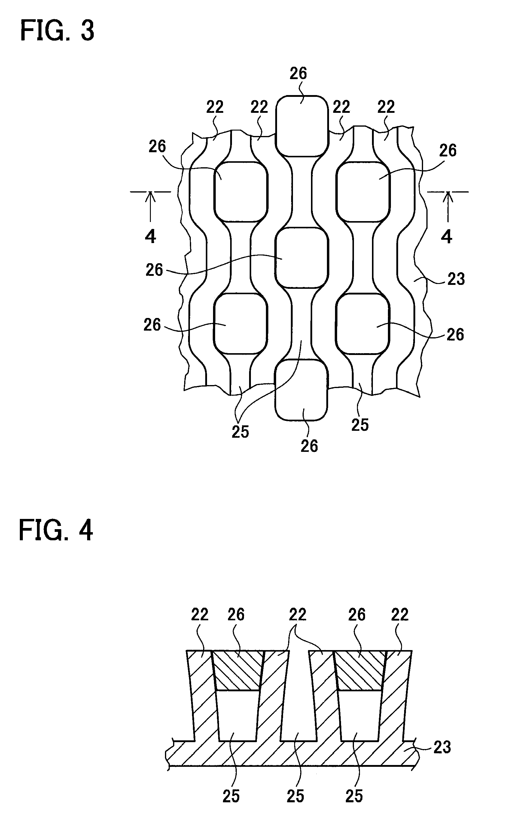
[0048]FIG. 1 is a plan view of a heat exchanger 21 in this embodiment. FIG. 2 is a cross-sectional view of the heat exchanger 21 taken along a line 2-2 in FIG. 1. FIG. 3 is an enlarged plan view showing only a part of the heat exchanger 21 circled by an elliptic chain line S1 in FIG. 1. FIG. 4 is a cross-sectional view of the heat exchanger 21 taken along a line 4-4 in FIG. 3.

[0049]As shown in FIGS. 1 to 4, this heat exchanger 21 includes a cooling fin 24 made of aluminum or aluminium consisting of a plurality of fin portions 22 and a base portion 23 supporting the fin portions 22. In this heat exchanger 21, the fin portions 22 are formed in straight parallel shapes, and a plurality of pins 26 each having a wider width than spaces 25 each formed between the fin portions 22 are pr...

second embodiment

[0063]A second embodiment of a heat exchanger and a manufacturing method thereof according to the present invention will be explained below in detail referring to accompanying drawings.

[0064]In the following explanation, similar or identical parts to those in the first embodiment are given the same reference signs and will not be explained in detail. The following explanation is therefore made with a focus on differences from the first embodiment.

[0065]FIG. 13 is a partial enlarged plan view of the heat exchanger in this embodiment, corresponding to FIG. 3. FIG. 14 is a cross-sectional view of the heat exchanger taken along a line 14-14 in FIG. 13. This embodiment differs from the first embodiment in the configuration of a plurality of pins. In this embodiment, specifically, a plurality of taper screws 27 are used as the pins. Each taper screw 27 is formed, on its top, with a cross groove 27a as shown in FIG. 13. Each taper screw 27 has a tapered outer shape as shown in FIG. 14. Tho...


PUM

PropertyMeasurementUnit
widthaaaaaaaaaa
displacementaaaaaaaaaa
taper shapeaaaaaaaaaa

Abstract

A heat exchanger is provided with a cooling fin including a plurality of fin portions and a base portion supporting the fin portions, and a plurality of pins press-fitted into the fin portions. In the heat exchanger, the pins each having a wider width than each space between the fin portions formed in advance in parallel straight shapes are press-fitted into the spaces in a direction from a top end of each fin portion toward the base portion. Accordingly, the fin portions are formed into corrugated shapes by plastic deformation, thereby fixing the pins between the fin portions in positions apart from the base portion. In each space, the pins are arranged at intervals in a longitudinal direction of each space. The pins arranged in adjacent spaces are placed with a displacement in alternating pattern.

Description

CROSS-REFERENCE TO RELATED APPLICATIONS[0001]This is a national phase application based on the PCT International Patent Application No. PCT / JP2009 / 059399 filed on May 22, 2009, the entire contents of which are incorporated herein by reference.TECHNICAL FIELD[0002]The present invention relates to a heat exchanger to be used in for example a cooling device for cooling a power converter, and a method of manufacturing the heat exchanger.BACKGROUND ART[0003]A power converter to be mounted in a hybrid electric vehicle, an electric vehicle, and others is conventionally arranged to include a semiconductor device and an electric component for power conversion. Since the semiconductor device and others generate a large amount of heat during operation, the converter is provided with a cooling device to ensure heat dissipation characteristics. Herein, the cooling device is configured to contain heat dissipating fins in a cooling case and cause a coolant (a cooling medium) to flow in the cooling...

Claims


Application Information

Patent Timeline
Patent Type & Authority Applications(United States)
IPC IPC(8): F28F7/00B21D53/02
CPCB23P15/26B23P2700/10F28F3/046F28F3/048F28F3/12F28F13/06Y10T29/4935H01L23/473F28F2215/10H01L2924/0002H01L21/4878Y10T29/49391H01L2924/00
Inventor KAKIUCHI, EISAKUTAKETSUNA, YASUJIMORINO, MASAHIROTAKANO, YUYA
Owner TOYOTA JIDOSHA KK
Why Eureka
Try Eureka