Contact protection circuit and high voltage relay comprising the same

a protection circuit and relay technology, applied in the field of electric switches, can solve the problems of limiting the lifetime of the switching device, contact wear, contamination of the area surrounding the switch, etc., and achieve the effect of prolonging the lifetime of the relay contacts

Active Publication Date: 2012-01-19
TYCO ELECTRONICS FRANCE +1
View PDF1 Cites 14 Cited by
  • Summary
  • Abstract
  • Description
  • Claims
  • Application Information

AI Technical Summary

Benefits of technology

[0032]The present invention aims at overcoming the disadvantages and shortcomings of the prior art techniques and an object thereof is to provide a contact protection circuit for suppressing an arc in mechanical switches and a high voltage relay having extended lifetime of the relay contacts.
[0035]Thus, by using an auxiliary switching mechanism that controls the time the auxiliary switch remains closed, the opening of the main switch and of the auxiliary switch can be automatically coordinated. Further, by delaying in time the opening of the auxiliary switch based on the characteristics of the PTC device, such as trip current and a speed for changing into the trip state, the present invention limits the time the auxiliary switch remains closed and still ensures that the current flowing through the auxiliary switch is sufficiently decreased below a safe value for which arcing is negligible or suppressed before the auxiliary switch is opened.
[0038]Since the current through the PTC device is greatly reduced when the PTC device trips to the high resistance state, the auxiliary switch can then be safely opened on a significantly reduced arcing current level.
[0042]The main coil protective element may be a high resistance resistor for dissipating quickly the remnant flow of current in the main coil. Thus, the contacts of the main switch open faster.
[0046]This has the advantage that the auxiliary switch is maintained automatically closed while the current flowing in the series arrangement is strong enough for producing arcing, and is automatically opened when this current falls below safe values.
[0054]This has the advantage that the same voltage circuit may be used for energizing both the main and the first coils. Thus, the operation of the switching device is simplified. Further, the operation of the two coils becomes synchronized in time.

Problems solved by technology

However, even if this limit can be shifted to higher voltages by the application of external magnets, the power dissipation in the unavoidable arc when the switch contacts are separated erodes the contact material and therefore limits the lifetime of the switching device.
The high temperatures reached during arcing may also cause melting of the contact portions or transfer of material between contacts which result in contact wear.
The contacts may develop uneven surfaces that mechanically lock the contacts when the switch is operated to open.
Another undesirable effect of arcing is the contamination of the areas surrounding the switch due to the evaporation and sputtering of contact material.
The overheating associated with arcing might also damage the surrounding areas and lead to the destruction of the device.
The high electric field established across the air gap between the switch contacts when these are separated for interrupting the supply of high voltage power to an electrical load produces an intense arc current between the separated contacts that may destroy the switch as well as the circuits to be protected.
The overcurrent in the PTC device causes the PTC device to quickly trip to its high resistance state, reducing the current to a very low level.
The use of a PTC device that quickly reaches that level may lower the required rating of the series switch.
However, a problem remains on how to ensure that the delay between the operation of the two switches is sufficient but not longer than required for suppressing arcing.
Otherwise, the PTC device may be damaged or cause damage to other components.
However, this has the disadvantage that the electrical switch arrangement must be customized for each specific application.
Finally, although the above proposed measures allow the reduction of the effective current / voltage at which the switches are opened for avoiding arcing, at present there are no solutions regarding how to control the time delay between operations of the switches and how to synchronize the switching tripping of the PTC and the galvanic isolation sequence.

Method used


Image

  • Contact protection circuit and high voltage relay comprising the same
  • Contact protection circuit and high voltage relay comprising the same
  • Contact protection circuit and high voltage relay comprising the same

Examples


Embodiment Construction

[0065]Advantageous embodiments of the present invention will now be described in further detail with reference to the accompanying drawings.

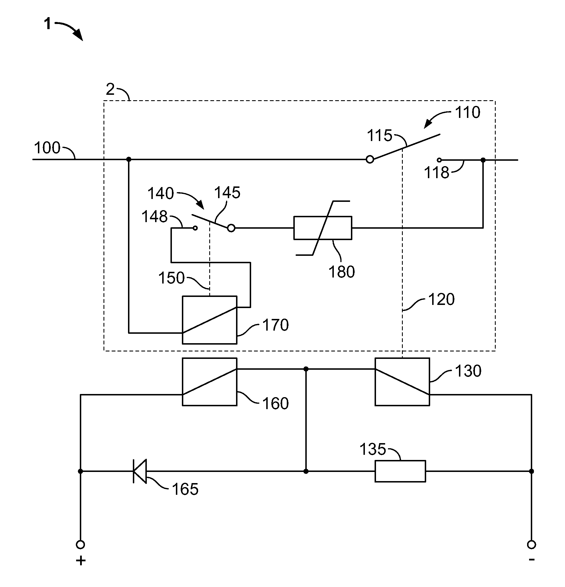
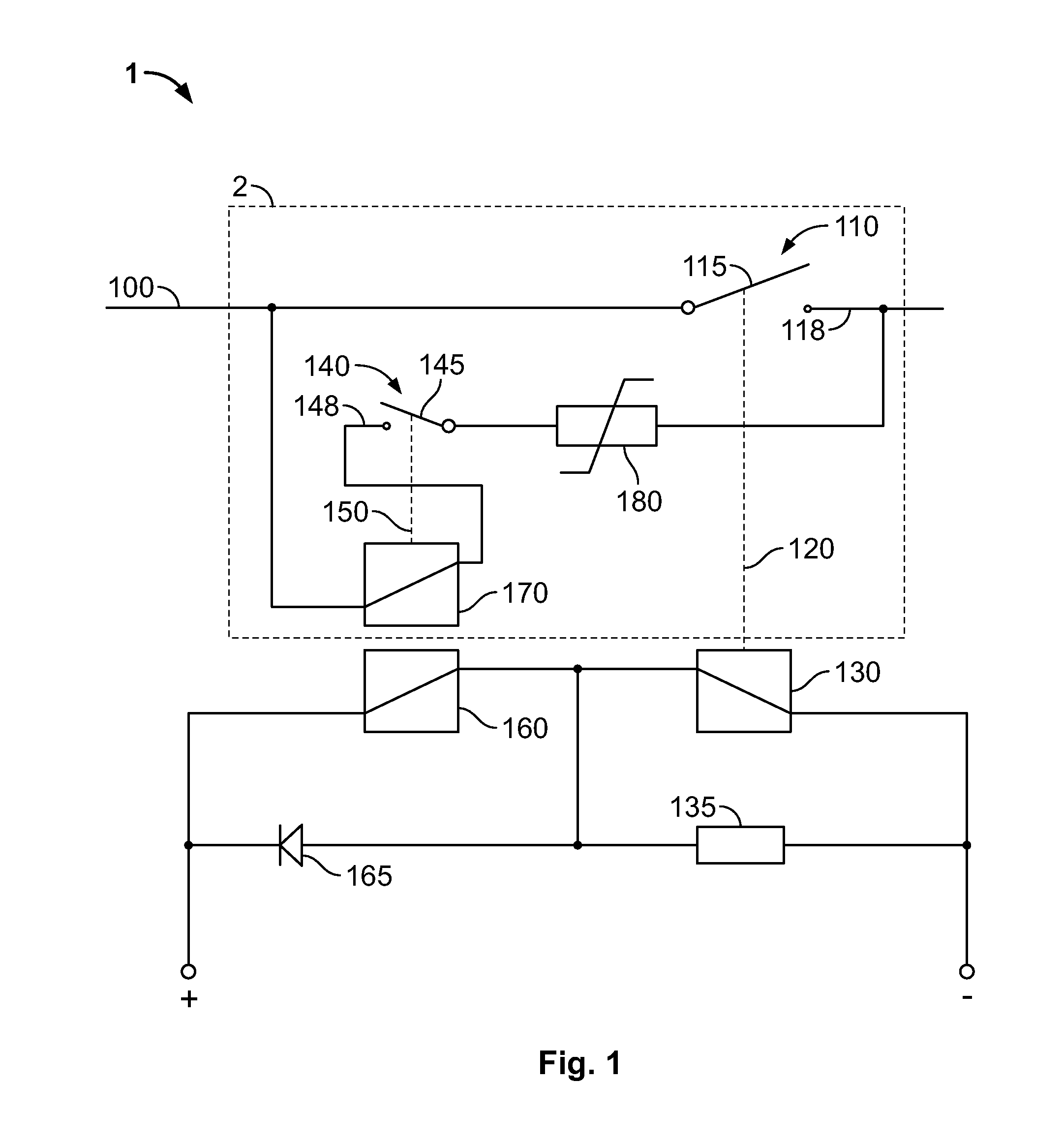
[0066]FIG. 1 shows a switching device 1 having an arc suppression circuit according to an exemplary embodiment of the present invention.

[0067]The switching device 1 can be connected in series between an electrical power supply and an electrical load (not shown) for controlling the flow of current through a load path 100.

[0068]The switching device 1 has a main switch 110 for electrically interrupting a flow of current through the load path 100 and a main switching mechanism for operating the main switch.

[0069]In the illustrated embodiment, the main switching mechanism together with the main switch 110 forms a main relay 120. The main switch 110, which will be referred to as main contact 110, is a mechanical switch having a movable contact member 115 and a fixed contact member 118. However, other contact combinations suitable for the same purpose ...


PUM


Abstract

The invention provides a switching device having a contact protection circuit for arcing suppression. The switching device comprises a main relay for interrupting a load path and a dual coil auxiliary having a high resistance coil and a low resistance coil that operate the switching of an auxiliary contact. The auxiliary contact is connected in series with a PTC device and the low resistance coil of the auxiliary relay in a series arrangement. The series arrangement is connected in parallel to the main contact. When the main relay opens, the auxiliary contact is maintained closed during a given time interval due to the magnetic flux generated by the low resistance coil. The given time interval depends on the transition of the PTC device to trip state. In another configuration, the dual coil relay is substituted by two auxiliary relays.

Description

TECHNICAL FIELD OF THE INVENTION[0001]The present invention relates to electrical switches, and more specifically, to contact protection circuits for suppressing arcing and switching devices such as high voltage relays comprising the same.BACKGROUND OF THE INVENTION[0002]Electrical switches are commonly used to control the flow of current in electrical circuits.[0003]Common types of electrical switches comprise mechanical contacts that can be made to open or close by manual operation or in response to an actuating mechanism, such as electrical actuation, magnetic induction, thermal activation, etc. These types of electrical switches, also called mechanical switches, can be found in various switching devices such as relays, circuit breakers, and ground fault interrupts.[0004]Without further measures, normal switches could only separate 12 to 20 V DC. However, even if this limit can be shifted to higher voltages by the application of external magnets, the power dissipation in the unav...

Claims


Application Information

Patent Timeline
Patent Type & Authority Applications(United States)
IPC IPC(8): H01H47/00
CPCH01H33/161H01H33/168H01H2033/163H01H50/543H01H47/18
Inventor KROEKER, MATTHIASEINHORN, JOERGGOZLAN, GILLES
Owner TYCO ELECTRONICS FRANCE
Why Eureka
Try Eureka