Fan structure

a technology of a fan and a frame, applied in the direction of positive displacement liquid engines, piston pumps, machines/engines, etc., can solve the problems of structural resonance, increased manufacturing costs, and inability to completely prevent structural resonance, so as to strengthen the frame, eliminate cogging torque, and hinder the effect of vibration

Inactive Publication Date: 2012-01-19
DELTA ELECTRONICS INC
View PDF7 Cites 1 Cited by
  • Summary
  • Abstract
  • Description
  • Claims
  • Application Information

AI Technical Summary

Benefits of technology

[0006]Accordingly, the invention provides a fan structure having a frame with a permeable stator structure therein to strengthen the frame and hinder vibrations thereof. A coil winding method of a slotless motor is used to form a slotless motor structure with a stator on an outer side and a rotor in an inner side of the stator. Therefore, a cogging torque can be eliminated and vibration of the fan structure can be decreased.
[0028]In conclusion, the frame of the present invention is made from plastic, and the silicon steel plate set is incorporated in the plastic frame. Hence, the frame of the present invention has great rigidity, like that of a metal frame, and great resiliency, like that of a plastic frame. Also, rigidity of the frame can hinder vibrations thereof. Meanwhile, because of the plastic frame, its appearance can be designed more beautifully and creatively.
[0029]Again, the rigidity of the frame can hinder vibrations thereof, because the frame is made from permeable material containing a high percentage of metal.
[0030]The frame of the present invention is a part of a stator thereof, and hence the stator is located at the outer side of the rotor assembly and the rotor assembly is located at the inner side of the stator. In the present invention, because the inner space of the sleeve is only used to receive the shaft and the bearing therein, the size of the sleeve becomes smaller, and the size of the blades can be larger. Therefore, the area of the airflow outlet can be maximized and hence the airflow output from the fan structure can be increased.

Problems solved by technology

Due to minimal structural rigidity of plastic frames, extrinsic forces may easily cause the frame to generate resonance.
However, the manufacturing costs would be increased.
Thus, structural resonance is not entirely prevented.

Method used


Image

  • Fan structure
  • Fan structure
  • Fan structure

Examples


Embodiment Construction

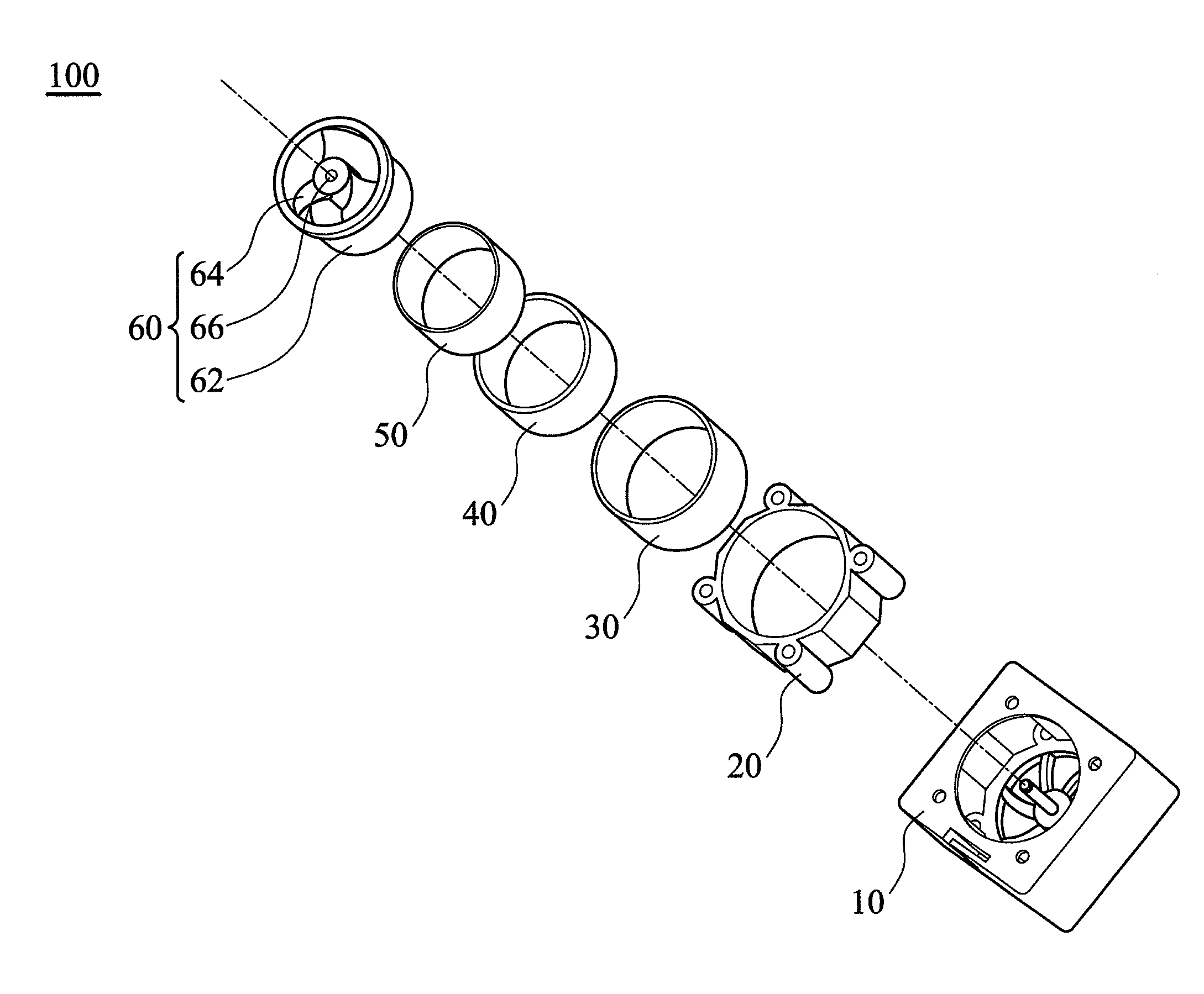
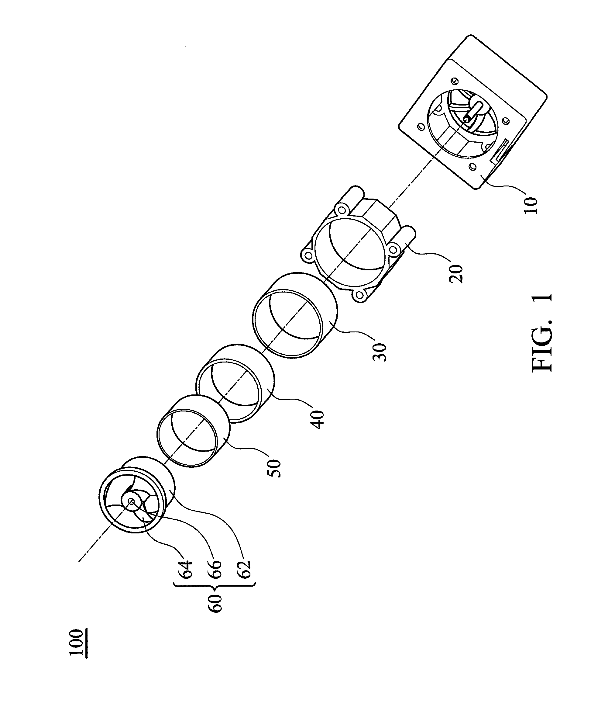
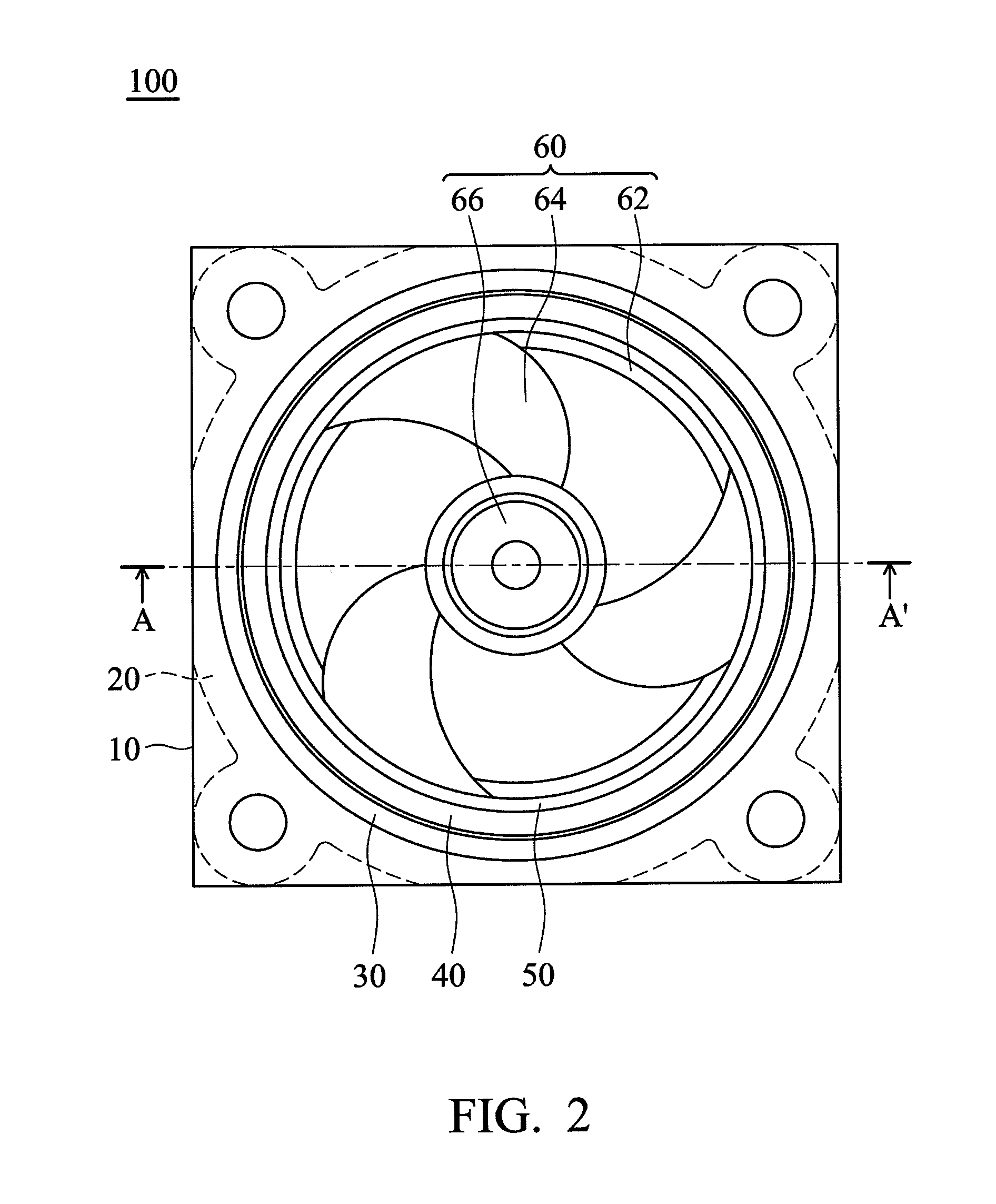
[0038]FIG. 1 is an exploded view of an embodiment of a fan structure of the present invention. FIG. 2 is a plane view of an assembled fan structure according to FIG. 1. FIG. 3 is a cross-sectional view of FIG. 2 along the line AA′. As shown in FIGS. 1, 2 and 3, the fan structure 100 of the present invention includes a frame 10, a silicon steel plate set (permeable element) 20, a coil 30, a permanent magnet 40, an iron ring 50 and a fan 60. The frame 10, the silicon steel plate set 20 and the coil 30 constitute a stator of the fan structure 100, and the permanent magnet 40, the iron ring 50 and the fan 60 are formed as a rotor assembly. The structure of the stator is described below.

[0039]The silicon steel plate set 20 is made from a plurality of arranged silicon steel plates by stamping. After the stamping process, the silicon steel plate set 20 is disposed in a mold of an injection-molding machine. Then, the molding material is injected into the mold to form the frame 10, wherein t...


PUM


Abstract

A fan structure includes a frame having an inner surface, a permeable element covering the inner surface of the frame, a coil surrounded by the permeable element and a rotor assembly disposed rotatably in the frame. The rotor assembly includes a plurality of blades coupled to a shaft and a permanent magnet enclosing the blades and facing the coil. The rotor assembly rotates along the shaft to generate airflow by means of the electromagnetic effect between the permanent magnet and the coil.

Description

CROSS-REFERENCE TO RELATED APPLICATIONS[0001]This Application claims priority of Taiwan Patent Application No. 099123377, filed on Jul. 16, 2010, the entirety of which is incorporated by reference herein.BACKGROUND OF THE INVENTION[0002]1. Field of the Invention[0003]The invention relates to a fan structure, and in particular, to a fan structure having a frame with a permeable stator structure therein to strengthen the frame.[0004]2. Description of the Related Art[0005]Usually, the frame of a traditional fan structure is made of plastics. Due to minimal structural rigidity of plastic frames, extrinsic forces may easily cause the frame to generate resonance. To prevent structural resonance, two solutions have been disclosed. One solution is to change the material of the frame to enhance structural rigidity and restrain vibration (for example, the frame can be made from aluminum). However, the manufacturing costs would be increased. Another solution is to change the cogging torque of ...

Claims


Application Information

Patent Timeline
Patent Type & Authority Applications(United States)
IPC IPC(8): F04B35/04
CPCF04D25/064H02K7/14H02K1/2733
Inventor LIANG, HUNG-YICHIU, YI-CHINGLEE, KUN-CHOUHUANG, SHIH-MING
Owner DELTA ELECTRONICS INC
Why Eureka
Try Eureka