Pipeline Debris Shearing Device

Active Publication Date: 2012-01-26
TDW DELAWARE INC
View PDF7 Cites 12 Cited by
  • Summary
  • Abstract
  • Description
  • Claims
  • Application Information

AI Technical Summary

Benefits of technology

[0005]A pipeline debris shearing device made according to this invention includes an elastomeric member that forms a peeling edge having a negative rake angle which engages and peels away debris from the internal wall of a pipeline. The peeling edge is formed at the point of meeting between a concave-shaped, curved forward face surface and a substantially straight outer peripheral surface. The elastomeric member, which has means for mounting to a pipeline pig, is oversized relative to the inside diameter of the pipe or pipeline so that in a pipeline-restrained position, the elastomeric member urges radially outward and the peeling edge engages the debris. Means may also be provided to assist the elastomeric member in urging radially outward. Because the elastomeric member is oversized, the member compensates for wear as it travels through the interior of the pipeline, peeling away debris.
[0007]An object of this invention is to provide a forwardly positioned, self sharpening, wear compensating, diameter conforming, paraffin and debris removing tool that may be mounted on a pipeline pig and used for the purpose of peeling away the paraffin and debris from the inner wall surface of a pipe or pipeline so as to avoid the progressive build-up of the paraffin and debris.

Problems solved by technology

One problem with current scraping disc or cup designs is that the disc is not self-sharpening.
Another problem is that the disc does not compensate for wear caused by continuous contact with the inner wall of the pipeline.
Still yet another problem is that the disc does not readily conform to the inside surface of the pipeline while at the same time providing for longer wear life.

Method used


Image

  • Pipeline Debris Shearing Device
  • Pipeline Debris Shearing Device
  • Pipeline Debris Shearing Device

Examples


Embodiment Construction

[0035]Preferred embodiments of a pipeline debris shearing device made and used according to this invention are described below with reference to the drawings and the following elements illustrated in the drawings:

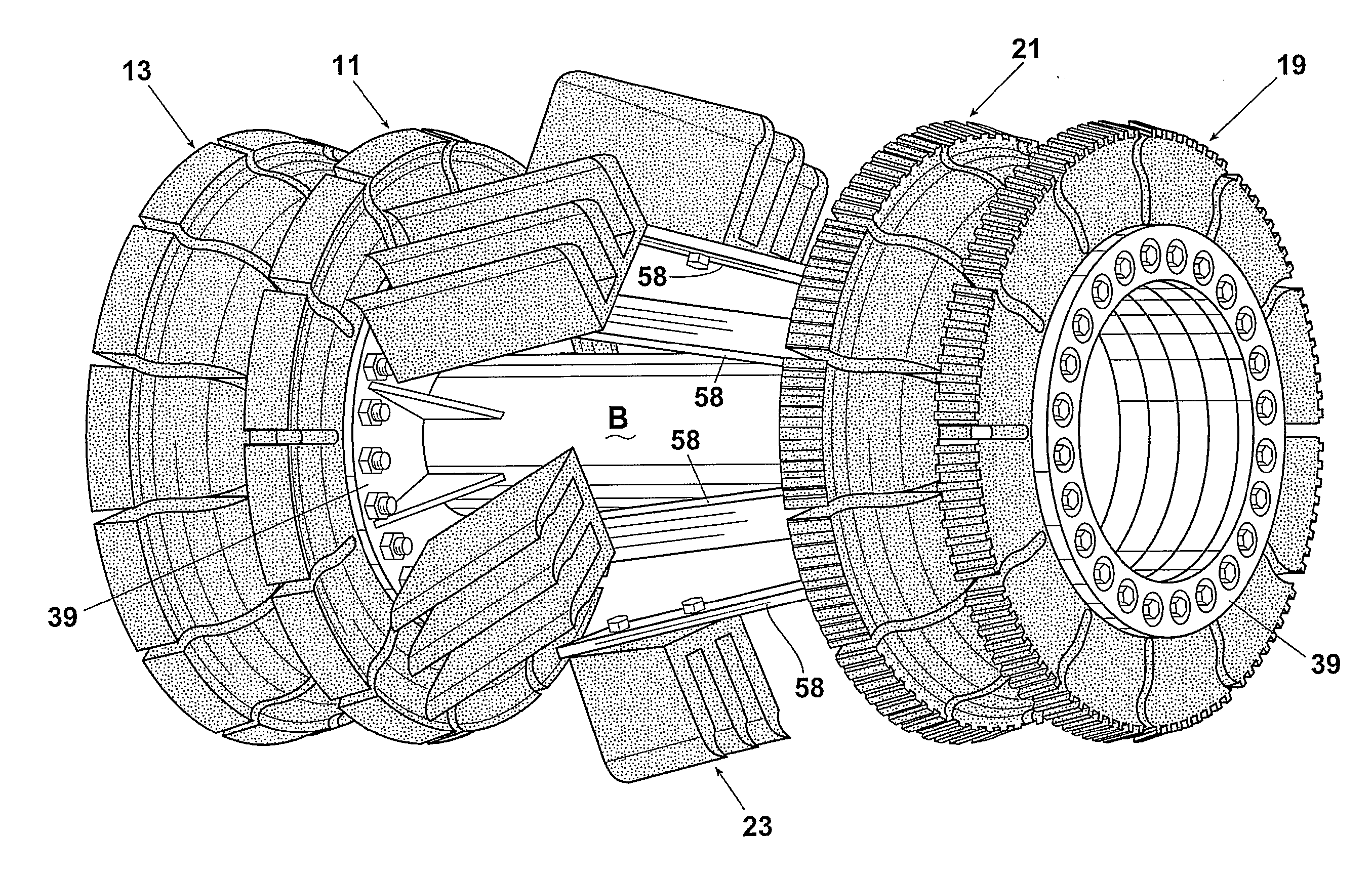
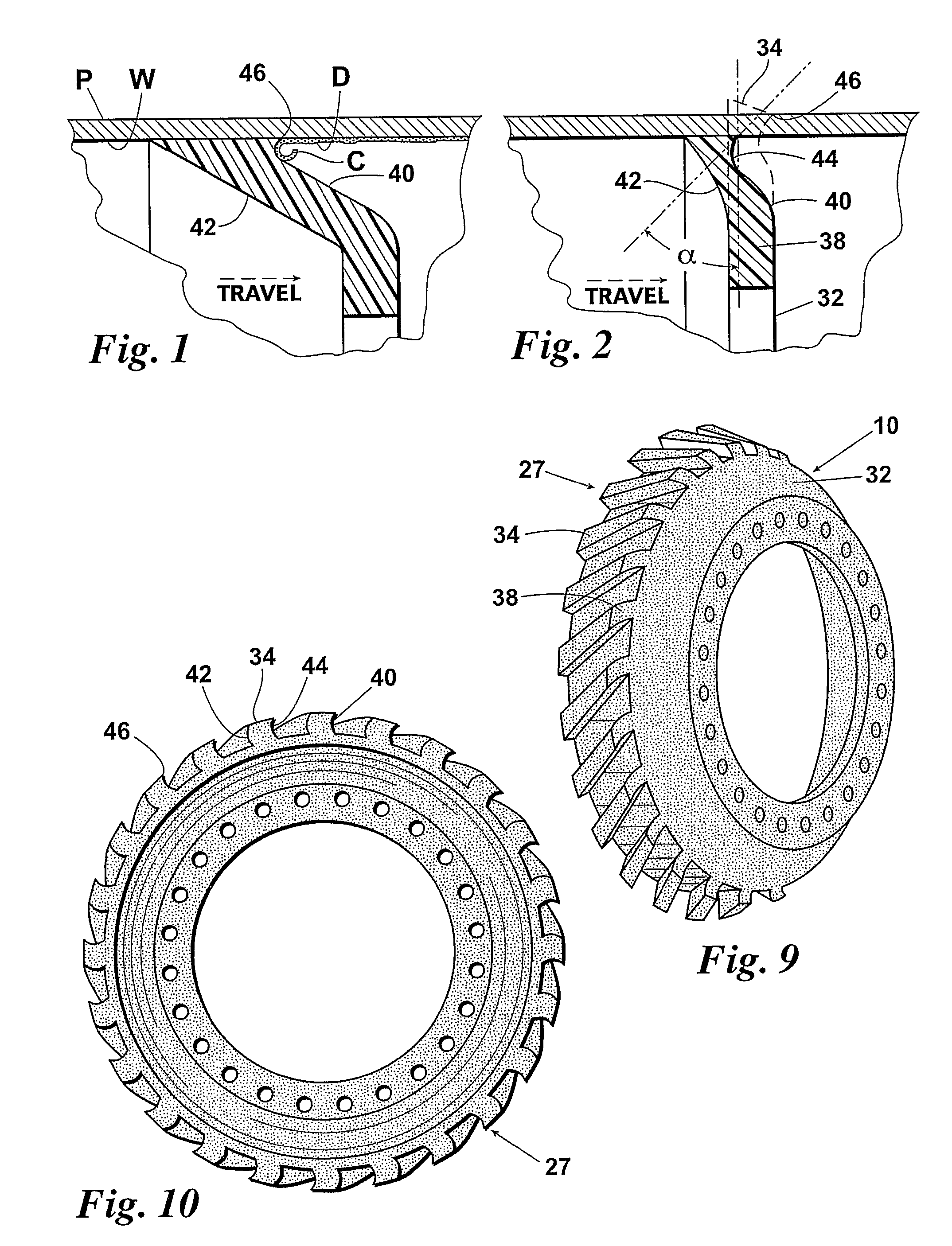
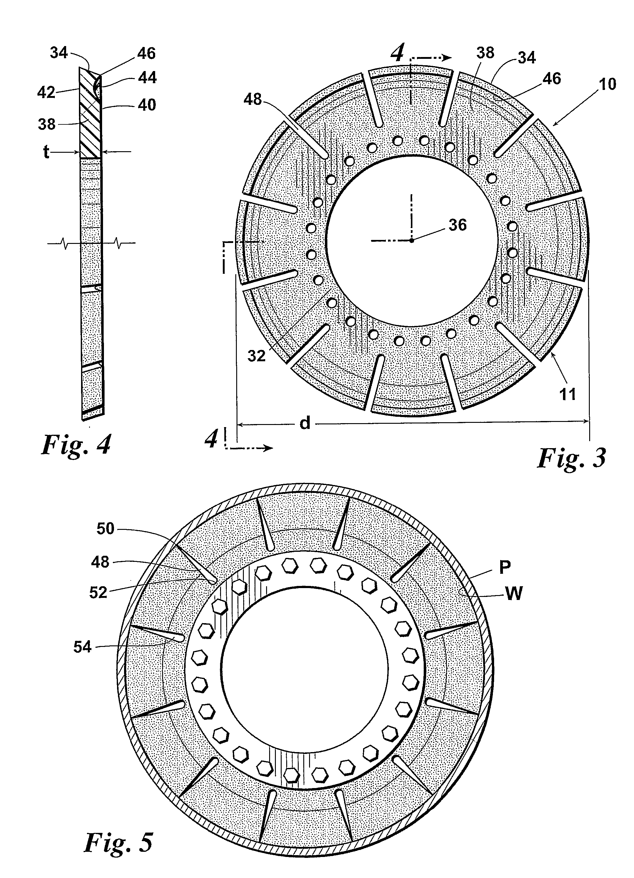
10 Elastomeric member11 Disc13 Cup15 Segmented disc17 Segmented cup19 Stripper disc21 Stripper cup23 Multi-ribbed blade25 Single blade27 Cup29 Foam pig32 Inner portion34 Outer peripheral surface36 Center38 Outer portion39 Attachment means40 Forward face42 Rearward face44 Curvature46 Point of 34 & 44 meeting / peeling edge48 Radial slot50 Upper end of 4852 Lower end of 4854 Bypass pathway56 Teeth58 Leaf type springs

[0036]Referring to the drawings and first to FIGS. 1 and 2, a pipeline debris shearing device made according to this invention has an elastomeric member 10 that forms a shearing or peeling edge 46 which peels away debris D such as paraffin from the inner wall surface W of a pipe or pipeline P as the pipeline pig to which elastomeric 10 is mounted moves forward under...


PUM


Abstract

A pipeline debris shearing device includes a forwardly positioned, self sharpening, wear compensating, diameter conforming elastomeric member that forms a peeling edge having a negative rake angle to peel away debris from the internal wall of a pipeline. The peeling edge is formed at the point of meeting between a concave-shaped, curved forward face surface and a substantially straight outer peripheral surface. Radial slots may be provided to lessen the force being exerted on the peeling edge and provide for bypass flow to carry away debris removed by the peeling edge. Spaced-apart narrow stripper teeth may be added to help in removing harder deposits of debris. The peeling edge may be arranged substantially perpendicular the central longitudinal axis of the pipeline pig or arranged oblique to it. Further, the peeling edge may spiral about at least a portion of the pipeline pig.

Description

BACKGROUND[0001]The present invention relates generally to pipeline pigs used for inspecting, maintaining and servicing piping systems and pipelines. More specifically, the present invention relates to pipeline pigs used for cleaning, namely, pigs with means for scraping and loosening debris from the inner wall of the pipe.[0002]Pipeline pigs are frequently employed in pipelines for a variety of services and are typically constructed to move by the force of fluid flow through a pipeline. The fluid may be in the form of water, petroleum products such as gasoline, diesel fuel, crude oil, propane, and so forth, or may be in the form of gas, such as natural gas. One of the primary reasons for sending a pig through a pipeline is to clean the interior of the pipeline of foreign matter, such as paraffin, dirt, sand, rocks, welding wire ends, scale, and water.[0003]A cleaning pig typically includes a body which is supported centrally within the pipeline, the body having an external diameter...

Claims


Application Information

Patent Timeline
IPC IPC(8): B08B9/04
CPCB08B9/0557
Inventor RANKIN, WILLIAM J.LOGAN, MATTHEW W.STRONG, ROBERT F.
Owner TDW DELAWARE INC
Why Eureka
Try Eureka