Hybrid power generation system and a method thereof

a power generation system and hybrid technology, applied in steam engine plants, machines/engines, mechanical equipment, etc., can solve the problems of reducing the performance of gas turbines, reducing the efficiency of conventional heat recovery systems, and simply dumped vast quantities of waste heat into the atmospher

Inactive Publication Date: 2012-01-26
GENERAL ELECTRIC CO
View PDF4 Cites 21 Cited by
  • Summary
  • Abstract
  • Description
  • Claims
  • Application Information

AI Technical Summary

Problems solved by technology

When waste heat is low grade, such as waste heat having a temperature, for example, below 300 degrees Celsius (570 degrees Fahrenheit), conventional heat recovery systems do not operate with sufficient efficiency to make recovery of energy cost-effective.
The net result is that vast quantities of waste heat are simply dumped into the atmosphere, ground, or water.
During warm days, the gas turbine's performance may be reduced due to elevated air temperature at an inlet of the compressor.
Interc...

Method used


Image

  • Hybrid power generation system and a method thereof
  • Hybrid power generation system and a method thereof
  • Hybrid power generation system and a method thereof

Examples


Embodiment Construction

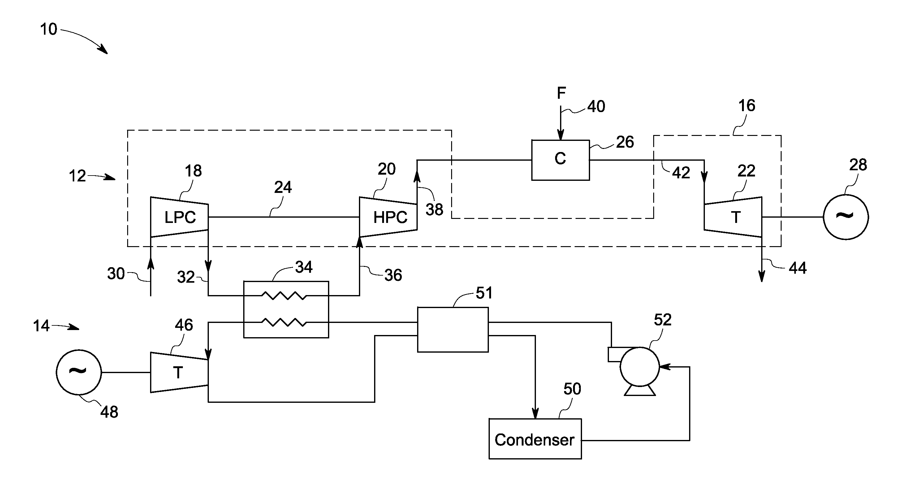
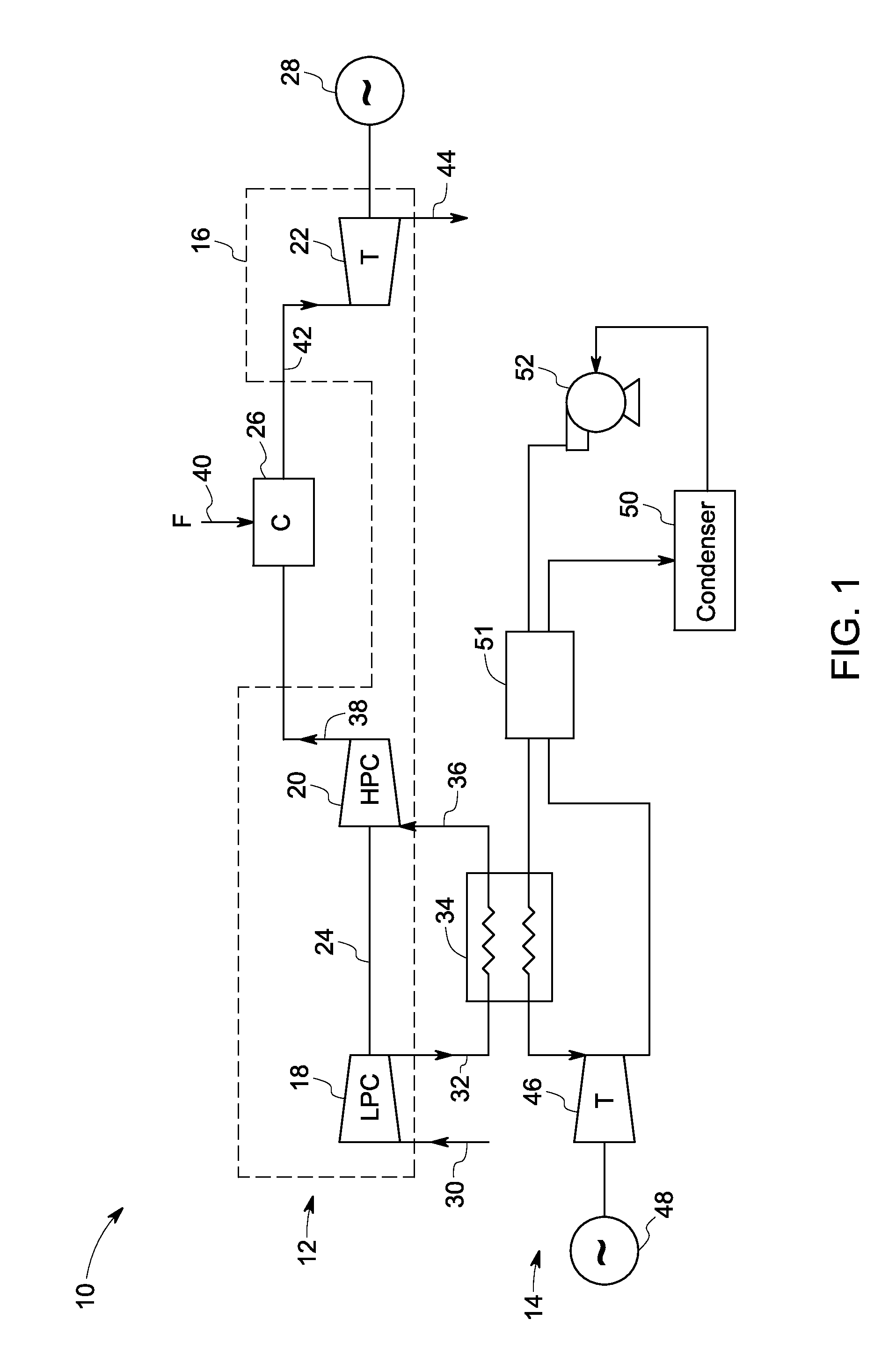
[0015]In accordance with the aspects of the present invention, a hybrid power generation system is disclosed. The hybrid power generation system includes a gas turbine engine system and a supercritical rankine cycle system. The gas turbine engine system includes a first compressor, an intercooler, a second compressor, combustor and a turbine. A first compressor is configured to compress an inlet airflow to produce a first outlet airflow at a first pressure. An intercooler is coupled to the first compressor and configured to cool the first outlet airflow exiting the first compressor to produce a second outlet airflow. A second compressor coupled to the intercooler and configured to compress the second outlet airflow exiting the intercooler to produce a third outlet airflow at a second pressure. The supercritical rankine cycle system is coupled to the intercooler to circulate a working fluid in heat exchange relationship with the first outlet airflow to heat the working fluid at a sup...


PUM


Abstract

A hybrid power generation system includes a gas turbine engine system and a supercritical rankine cycle system. The gas turbine engine system includes a first compressor, an intercooler, and a second compressor. A first compressor is configured to compress an inlet airflow to produce a first outlet airflow at a first pressure. An intercooler is coupled to the first compressor and configured to cool the first outlet airflow exiting the first compressor to produce a second outlet airflow. A second compressor is coupled to the intercooler and configured to compress the second outlet airflow exiting the intercooler to produce a third outlet airflow at a second pressure. The supercritical rankine cycle system is coupled to the gas turbine engine system. The supercritical rankine cycle system is coupled to the intercooler to circulate a working fluid in heat exchange relationship with the first outlet airflow to heat the working fluid at a supercritical pressure from a first temperature to a second temperature above a critical temperature of the working fluid and to cool the first outlet airflow exiting the first compressor.

Description

BACKGROUND[0001]The invention relates generally to power generation systems, and more particularly to a hybrid power generation system having a gas turbine system and a rankine cycle system.[0002]Enormous amounts of waste heat are generated by a wide variety of industrial and commercial processes and operations. Example sources of waste heat include heat from space heating assemblies, steam boilers, engines, and cooling systems. When waste heat is low grade, such as waste heat having a temperature, for example, below 300 degrees Celsius (570 degrees Fahrenheit), conventional heat recovery systems do not operate with sufficient efficiency to make recovery of energy cost-effective. The net result is that vast quantities of waste heat are simply dumped into the atmosphere, ground, or water.[0003]Generally, in a gas turbine engine system, air is compressed in a compressor or a multi-stage compressor. Compressed air is mixed with fuel such as natural gas, light fuel oil, or the like and ...

Claims


Application Information

Patent Timeline
IPC IPC(8): F02C1/00F02C6/00
CPCF01K23/08F02C7/143F01K25/10
Inventor FREUND, SEBASTIAN WALTERFREY, THOMAS JOHANNESHUCK, PIERRE SEBASTIEN
Owner GENERAL ELECTRIC CO
Why Eureka
Try Eureka