Weir grate

a technology of weir grate and grate plate, which is applied in the field of weir grate, can solve the problems of increased production time, less volume output, and thicker walled products, and achieves the effects of reducing production costs, increasing production time, and increasing production costs

Inactive Publication Date: 2012-01-26
SWANSTON WILLIAM FRANCIS
View PDF6 Cites 19 Cited by
  • Summary
  • Abstract
  • Description
  • Claims
  • Application Information

AI Technical Summary

Benefits of technology

[0049]In one embodiment the thickness and width of the flange of the outlet pipe can be selected to correspond to the depth and width of the step whereby, when so mounted, an in-use upperside of the flange sits flush with an in-use upperside of a next adjacent step. This configuration tends to prevent the pooling of water flowing through the weir grate.
[0050]In one embodiment, a retaining ring can be fastened to surround the outlet pipe at an underside of the step, opposite to the step upperside. This ring provides a tight fit against the outlet pipe to the base and can be retained by a clip that is spot welded to the pipe. This in turn fastens the outlet pipe to the base tray. The ring may alternatively take the form of a mating sleeve that further comprises a flange projecting laterally from and around an upper periphery of the sleeve, so that the flange sits at the underside of the step when fastened to surround the outlet pipe.

Problems solved by technology

However, compared to die-casting, investment casting results in increased production time, lower volume output, more costly casting raw materials, thicker walled products and, often, the need for a subsequent wall straightening step.

Method used


Image

  • Weir grate
  • Weir grate
  • Weir grate

Examples


example 1

Method of Constructing a Weir Grate

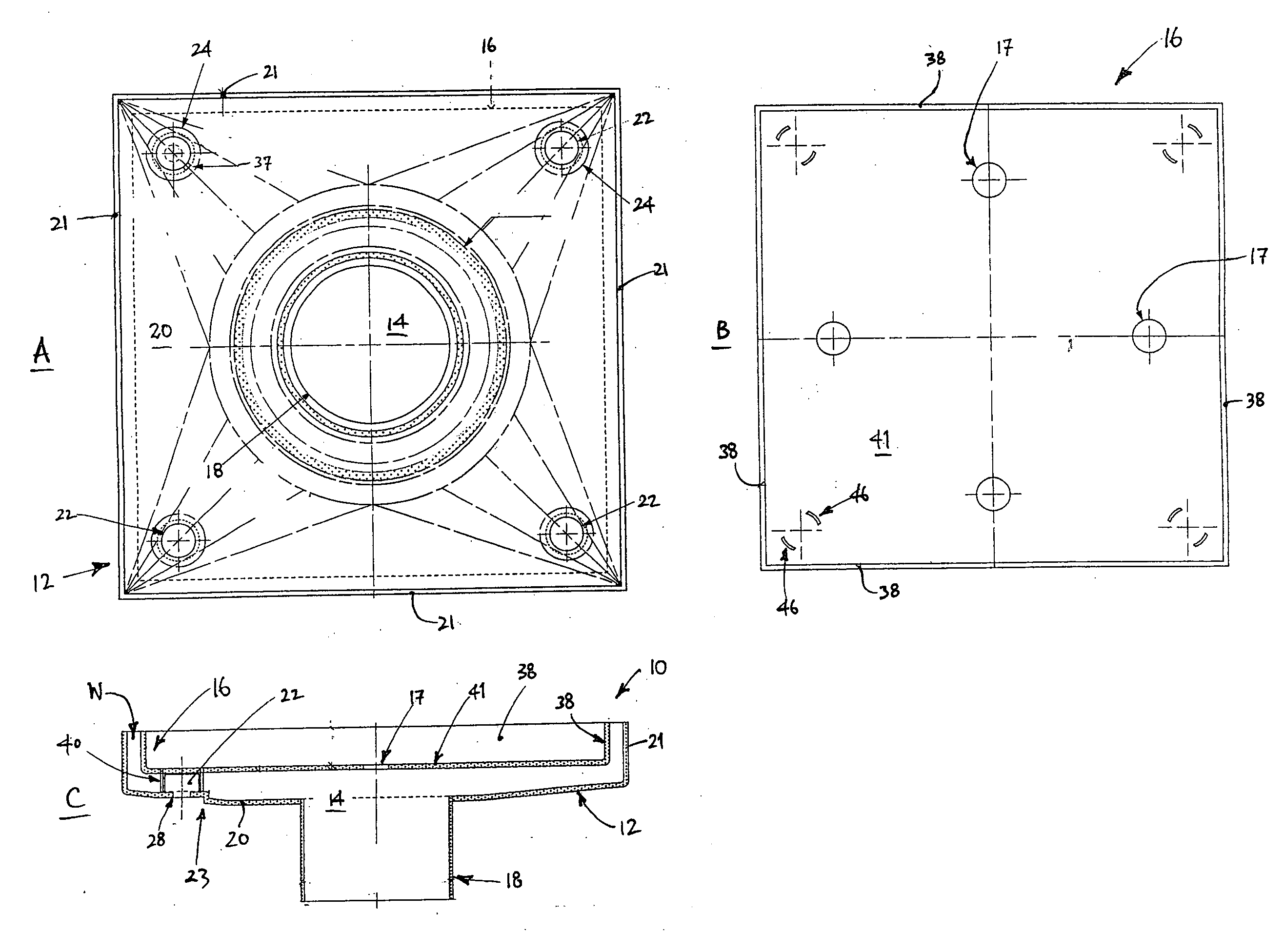
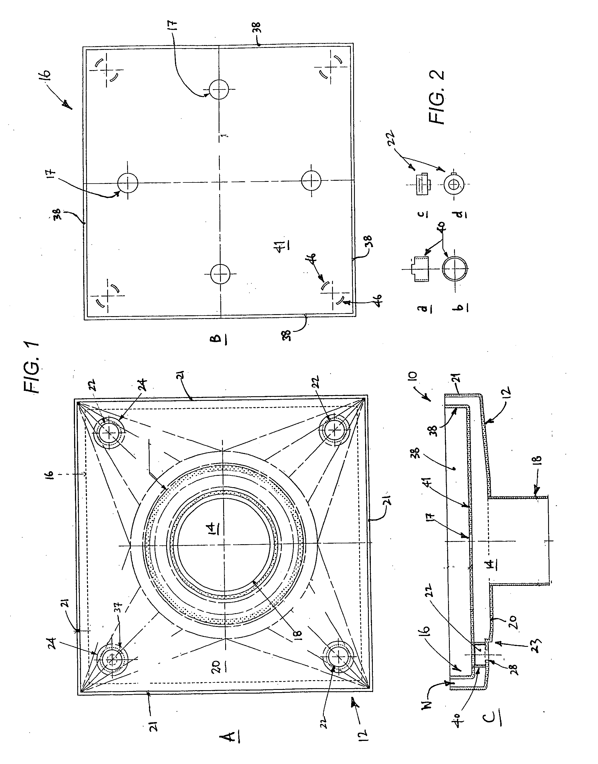
[0130]A method of constructing one of the weir grates 10, 10′, 10″ described comprised the following steps:[0131]1. Determining, on a large stainless steel sheet, locations for the base tray 12 and infill tray 16, and for the apertures 28, 46 and holes 14, 17.[0132]2. Punching or cutting (e.g. by laser) the respective apertures and holes, at locations that correspond to each of the pedestals 22 and tube supports 40, in suitably sized metal sheets for each of the base and infill trays.[0133]3. Die-press or laser cutting-out the metal sheets for each of the base and infill trays.[0134]4. Press-forming each of the base and infill trays from their respective metal sheets, so as to form the corners C by the folding up F of the walls (21 or 38) as shown in FIG. 12. During such press-forming the slope in the plate 20, 20″ and the bosses 24 etc can be defined, and the steps 23, 50, 62, 64 can be stamped into the plate.[0135]5. Welding together and the grin...

example 2

Method of Installing a Weir Grate

[0147]A method of installing one of the pre-packaged weir grates 10, 10′, 10″, 100 described above comprised the following steps:[0148]1. Detaching the infill tray from the base tray so that each tube support 40, 140 releases its respective pedestal therefrom.[0149]2. Connecting the outlet pipe 18 (or 70, 74, 118) of the base tray to a drainpipe.[0150]3. Affixing the base tray in a floor (e.g. using a tiling cement, or other adhesive or fastener).[0151]4. Adhesively fastening an overlay (e.g. a tile) in / to the infill tray.[0152]5. Tiling (or otherwise covering) the floor up to (or over the flange 180 of) the base tray.[0153]6. Re-positioning the infill tray in the base tray.

[0154]In this installation method a base tray with the right-sized outlet pipe for the given drainpipe diameter is prior-selected.

[0155]In this installation method the overlay may comprise a tile (or a part thereof) that matches the surrounding tiles used on the floor, or may comp...


PUM

PropertyMeasurementUnit
sizeaaaaaaaaaa
diameteraaaaaaaaaa
thicknessaaaaaaaaaa

Abstract

A weir grate (10, 100) comprises a base tray (12, 112) having an outlet (14, 114), and an infill tray (16, 116) positionable in the base tray. The base tray comprises a plurality of discretely positioned posts (22, 122) projecting upwardly therefrom in use. The infill tray comprises a plurality of correspondingly positioned locators (40, 140) projecting downwardly therefrom in use. Each locator is arranged for engaging with a respective post when the infill tray is positioned in the base tray.

Description

TECHNICAL FIELD[0001]A weir grate and methods for constructing and installing the grate are disclosed. The configuration of the grate is such that it may be rapidly formed from sheet metal, making it cost effective to produce.BACKGROUND ART[0002]Weir grates provide a design alternative to floor-mounted drainage grates (also known as drainage wastes) that comprise multiple holes, often forming a pattern. Weir and drainage grates are predominantly die-cast because this technique allows for low-cost and mass production of grates of acceptable quality, using brass, zinc and other non-ferrous metals. The technique is able to produce complicated grate shapes, but requires an electro-plating step to obtain a grate with a surface appearance that is acceptable to a consumer (e.g. a chrome-like polished surface finish).[0003]To enable grates to be directly formed from higher melting point ferrous metals such as stainless steel, investment casting has been employed. However, compared to die-ca...

Claims


Application Information

Patent Timeline
Patent Type & Authority Applications(United States)
IPC IPC(8): E03C1/12B21D31/00B23P11/00E03C1/22
CPCE03F5/06E03F5/0407Y10T29/49826E03C2201/00E03C1/22
Inventor SWANSTON, WILLIAM FRANCIS
Owner SWANSTON WILLIAM FRANCIS
Why Eureka
Try Eureka