Passive power management and battery charging for a hybrid fuel cell / battery system

a hybrid fuel cell and battery technology, applied in the field of electric fuel cells, can solve the problems of system weight, volume and efficiency, loss associated, % efficiency, etc., and achieve the effect of low internal resistan

Active Publication Date: 2012-01-26
PLUG POWER AUTONOMOUS TECH INC
View PDF2 Cites 36 Cited by
  • Summary
  • Abstract
  • Description
  • Claims
  • Application Information

AI Technical Summary

Benefits of technology

[0025]In one example, the ba...

Problems solved by technology

This is a disadvantage for system weight, volume and efficiency.
The issue with this approach is that there are losses associated (˜90% efficiency), and therefore the stack voltage must be significantly higher than the battery charge voltage to ...

Method used


Image

  • Passive power management and battery charging for a hybrid fuel cell / battery system
  • Passive power management and battery charging for a hybrid fuel cell / battery system

Examples


Embodiment Construction

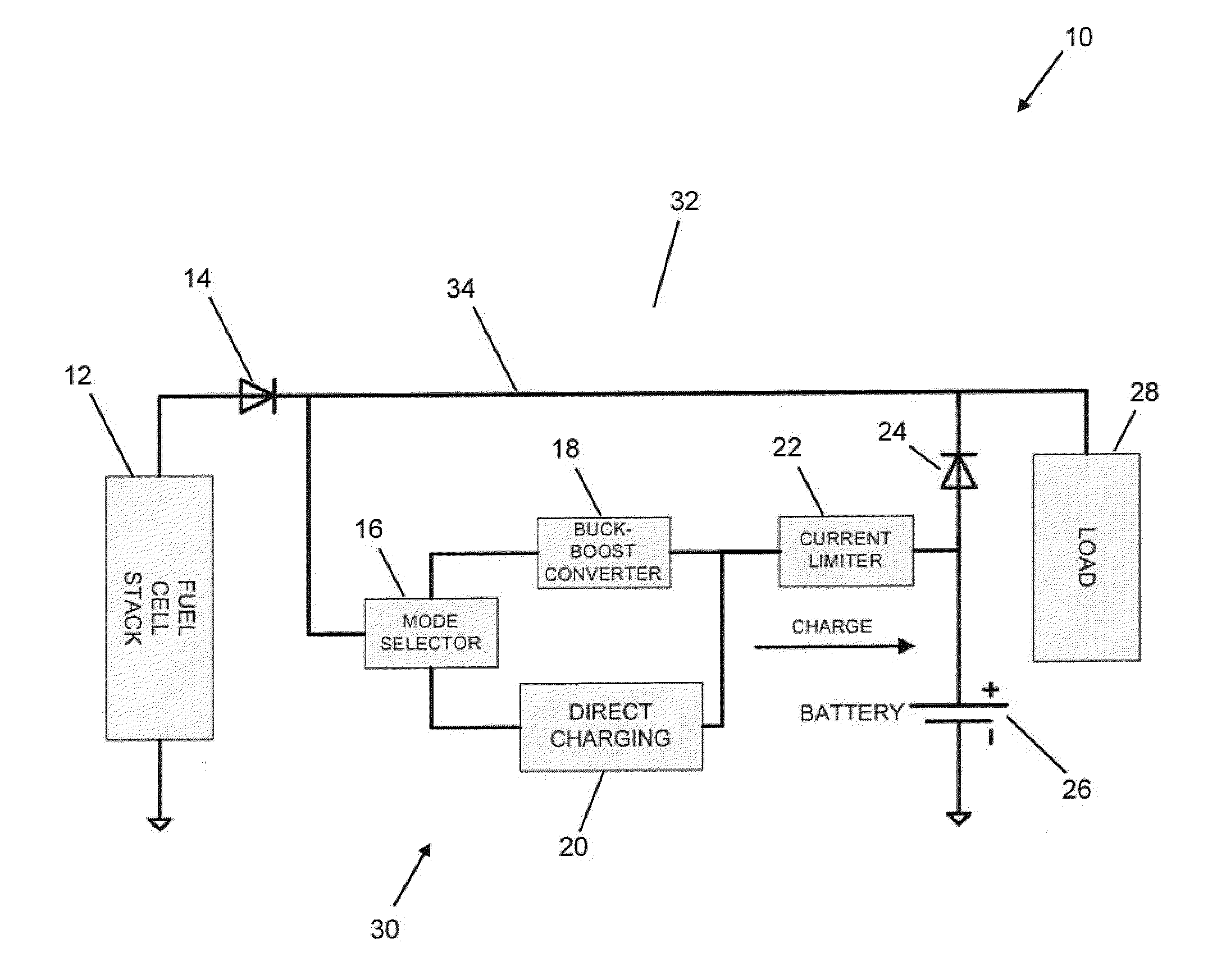
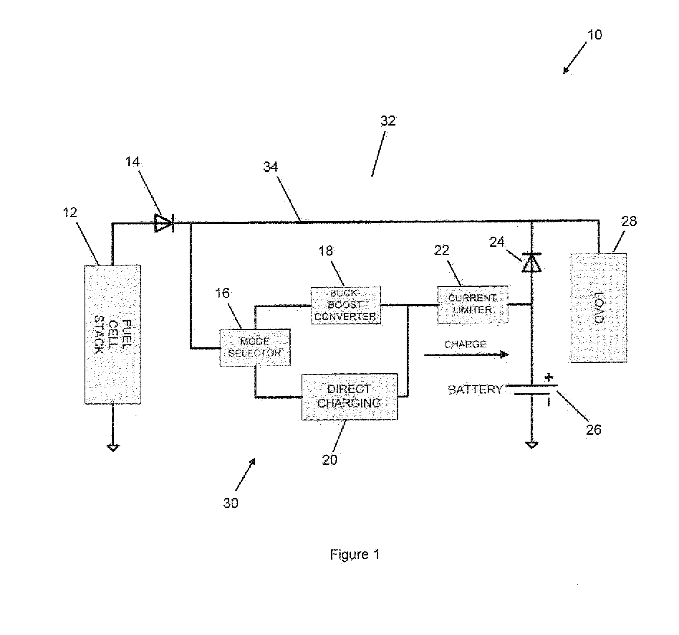
[0043]Referring now to FIG. 1, a device for passively managing a fuel cell / hybrid power system is shown generally at 10. The device 10 comprises a fuel cell stack 12 that is electrically connected in a parallel configuration to a battery 26. The battery 26 has low internal resistance.

[0044]Still referring to FIG. 1, the device 10 includes a passive control circuit 30 which is connected between the fuel cell stack 12 and the battery 26. The circuit 30 comprises a mode selector 16, a buck-boost DC / DC converter circuit 18, a direct charge circuit 20, and a current limit circuit 22. The mode selector 16 passively selectively electrically connects either the buck-boost converter circuit 18 or the direct charge circuit 20 to the battery 26. A current limit circuit 22 electrically connects the buck-boost converter 18 or the direct charger 20 to the battery 26. The mode selector 16, the buck-boost converter circuit 18, the direct charge circuit 20, and the current limit circuit 22 are elect...


PUM


Abstract

Disclosed herein is a circuit for passively managing power between a fuel cell stack and a battery in a hybrid system. The circuit includes a buck-boost converter circuit, a direct charge circuit; and a network which interconnects them. The network is configured so that in response to a voltage level in the network being lower than or equal to a maximum battery charge voltage, the battery is charged via the direct charge circuit; and in response to another voltage level in the network which is higher than the maximum battery charge voltage, the battery is charged via the buck-boost converter circuit. Also disclosed is a device incorporating the circuit and a method of passively managing power.

Description

CROSS-REFERENCE TO RELATED APPLICATIONS[0001]Priority from previously filed U.S. provisional patent application Ser. No. 61 / 400,269, filed on Jul. 26, 2010, is hereby claimed.TECHNICAL FIELD[0002]The present generally concerns electrochemical fuel cells and more particularly to passive power management and battery charging for a hybrid fuel cell / battery system.BACKGROUND[0003]Polymer electrolyte membrane or proton exchange membrane (PEM) fuel cells have intrinsic benefits and a wide range of applications due to their relatively low operating temperatures (room temperature to approximately 80° C.). The active portion of a PEM is a membrane sandwiched between an anode and a cathode layer. Fuel containing hydrogen is passed over the anode and oxygen (air) is passed over the cathode. The reactants, through the electrolyte (membrane), react indirectly with each other generating an electrical voltage between the cathode and anode. Typical electrical potentials of PEM cells can range from ...

Claims


Application Information

Patent Timeline
IPC IPC(8): H01M10/46
CPCH01M10/44H01M10/46H01M10/48H02J2001/004H01M16/003H02J1/06H02J7/34H01M16/00H02J2300/30H02J2310/40Y02E60/50Y02E60/10H02J7/342H01M8/04567H01M8/24H01M10/446H01M12/08
Inventor JONES, THOMAS DAVIDKIM, SEYOUNG
Owner PLUG POWER AUTONOMOUS TECH INC
Why Eureka
Try Eureka