Lens unit and vehicle-mounted infrared lens unit

a technology for infrared imaging and lens units, which is applied in the field of lenses, can solve the problems of degrading the performance of infrared imaging apparatuses, temperature change, and change in optical characteristics of vehicle-mounted infrared lens units, and achieve the effect of increasing the size of the lens unit and increasing the cos

Active Publication Date: 2012-01-26
SUMITOMO ELECTRIC IND LTD
View PDF1 Cites 56 Cited by
  • Summary
  • Abstract
  • Description
  • Claims
  • Application Information

AI Technical Summary

Benefits of technology

[0054]According to the present invention, the characteristics of components of the lens unit being expanded or reduced with a temperature change of the surrounding environment are utilized to move the lens of the lens unit in the axial direction in the barrel in response to a temperature change, so that the focal shift of the lens unit caused by such factors as a change in refractive index of the lens due to a temperature change can be cancelled and

Problems solved by technology

Since the temperature in the surrounding environment around the infrared imaging apparatus mounted on a vehicle varies widely, a change in optical characteristics of vehicle-mounted infrared lens unit

Method used


Image

  • Lens unit and vehicle-mounted infrared lens unit
  • Lens unit and vehicle-mounted infrared lens unit
  • Lens unit and vehicle-mounted infrared lens unit

Examples


first embodiment

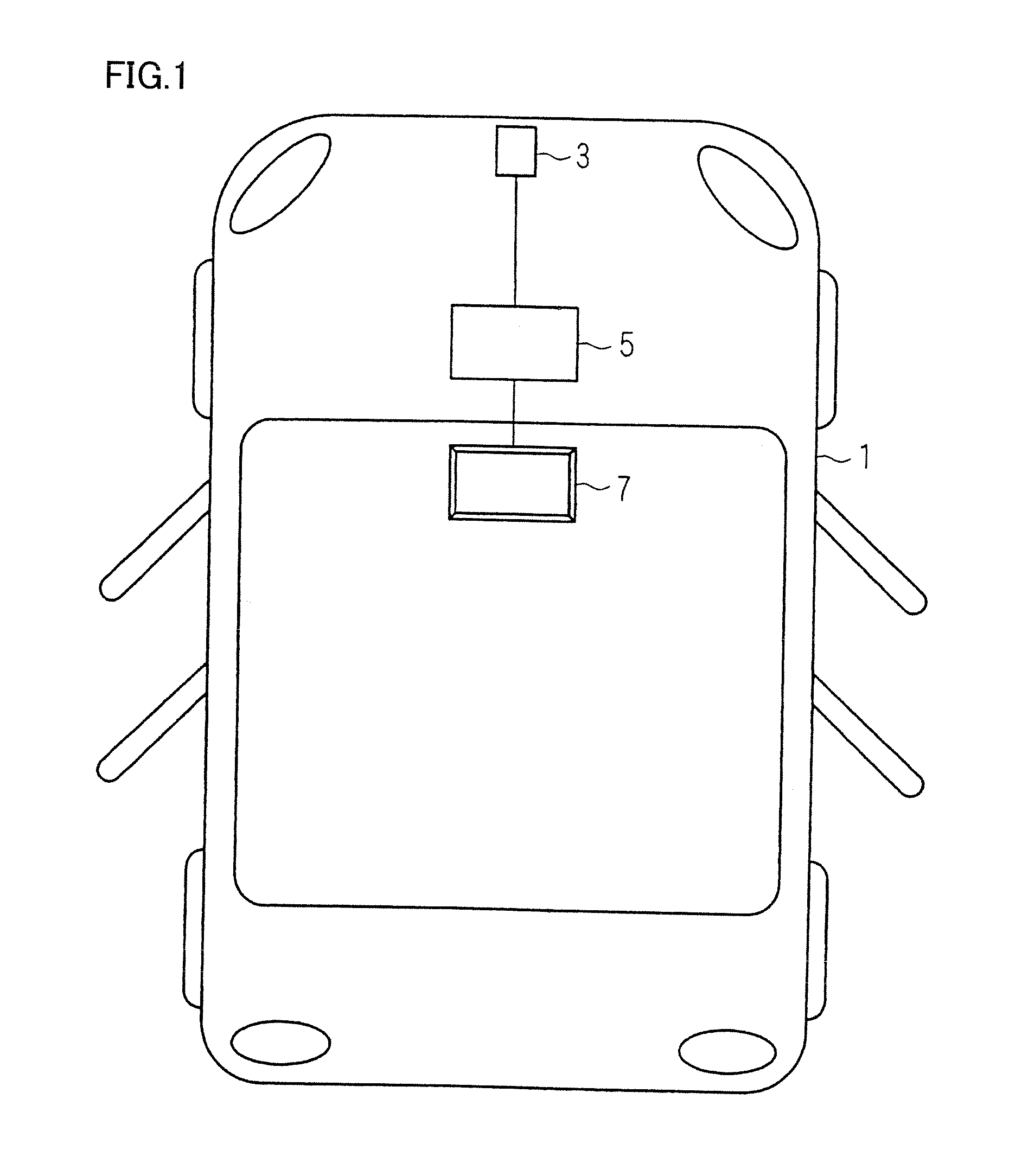
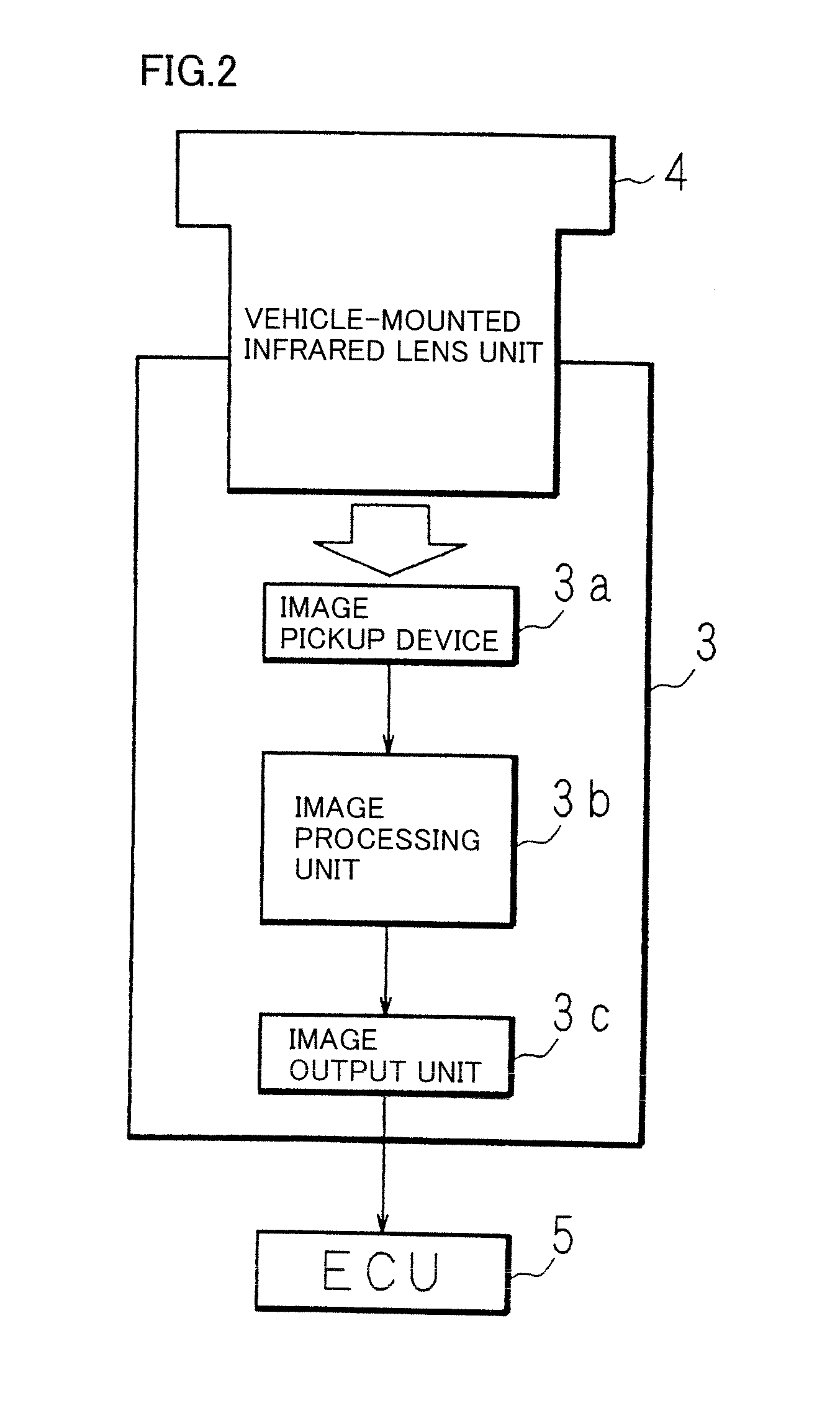
[0159]In the following, the present invention will be specifically described based on the drawings showing the embodiments thereof. FIG. 1 is a diagram showing an exemplary vehicle on which an infrared imaging apparatus is mounted. The figure shows a vehicle 1, in which an infrared imaging apparatus 3 is mounted at a front portion of a body of vehicle 1 (for example, in the vicinity of a front bumper). Infrared imaging apparatus 3 can receive infrared light to pick up an image and outputs an image obtained by picking up an image to an ECU (Electronic Control Unit) 5 mounted on vehicle 1.

[0160]ECU 5 is mounted at an appropriate place of vehicle 1, performs a variety of image processing on the image input from infrared imaging apparatus 3, and performs processing for displaying the image on a display 7. Display 7 is mounted in the vicinity of the driver's seat of vehicle 1 and displays an image input from ECU 5. ECU 5 may perform processing of detecting a pedestrian from the image pic...

second embodiment

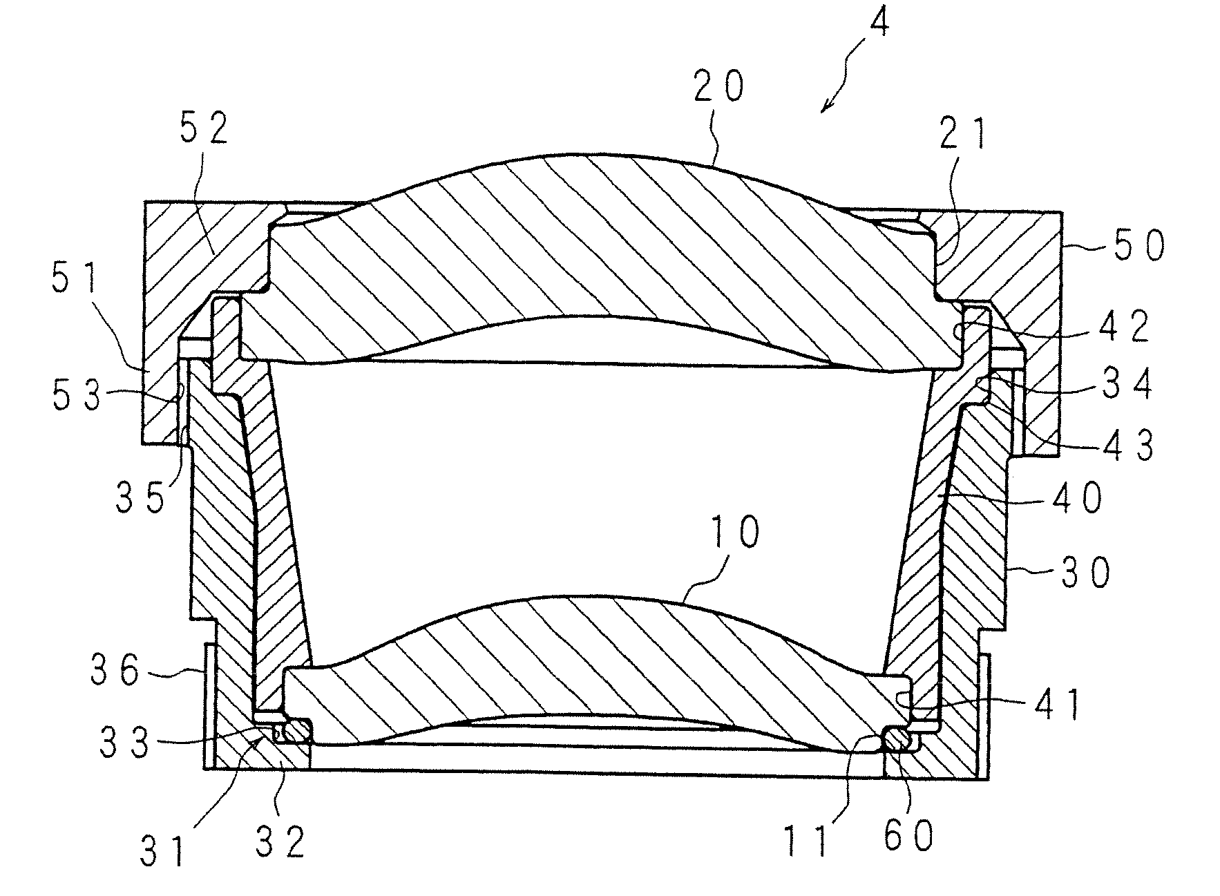
[0220]FIG. 16 is a schematic cross-sectional view showing a configuration of a vehicle-mounted infrared lens unit 204 in accordance with a second embodiment of the present invention. Similar to vehicle-mounted infrared lens unit 4 in accordance with the first embodiment, vehicle-mounted infrared lens unit 204 in accordance with the second embodiment is configured such that a first infrared lens 210, a spacer 240, and a second infrared lens 220 are inserted into a barrel 230 and they are retained by a lens retainer 250 to be held in barrel 230.

[0221]First infrared lens 210 and second infrared lens 220 are each formed in the shape of a disk and each are a meniscus lens having a convex surface on the front side and having a concave surface on the rear side. The peripheral portions of the front and rear surfaces of second infrared lens 220 are formed to be smooth. The peripheral portion of the front side of first infrared lens 210 is formed to be smooth. The peripheral portion of the re...

third embodiment

[0238]FIG. 18 is a schematic cross-sectional view showing a configuration of a vehicle-mounted infrared lens unit 304 in accordance with a third embodiment of the present invention. The vehicle-mounted infrared lens unit in the foregoing first and second embodiments includes two infrared lenses, wherein the first infrared lens is pressed by the thermal expansion of the spacer to move inside the barrel. By contrast, vehicle-mounted infrared lens unit 304 in accordance with the third embodiment includes only one infrared lens 310 and therefore does not include a spacer provided between two infrared lenses. Vehicle-mounted infrared lens unit 304 in accordance with the third embodiment is configured such that infrared lens 310 is inserted into a barrel 330 and is retained by a lens retainer 350 and a spring member (pressing member) 370 to be held in barrel 330.

[0239]Infrared lens 310, formed in the shape of a disk, is a meniscus lens having a convex surface on the front side and having ...


PUM


Abstract

Provided are a lens unit and a vehicle-mounted infrared lens unit capable of correcting a focal shift due to a temperature change without increasing the apparatus size, complicating a production process, and increasing the costs. In a vehicle-mounted infrared lens unit 4 configured such that a plurality of infrared lenses are held by a barrel 30 and a spacer 40 is interposed between two infrared lenses, a first infrared lens 10 is held sandwiched between the spacer 40 and a lens holding portion 31 of the barrel 30. The spacer 40 and the barrel 30 are formed of materials having different thermal expansion coefficients. An O-ring 60 is interposed between a lock portion 32 of the lens holding portion 31 and the first infrared lens 10. Thermal expansion of the spacer 40 allows the first infrared lens 10 to move in the axial direction against the elastic force of the O-ring 60. When the spacer 40 is shrunken, the elastic force of the O-ring 60 allows the first infrared lens 10 to move in the opposite direction.

Description

RELATED APPLICATIONS[0001]This application is the U.S. National Phase under 35 U.S.C. §371 of International Application No. PCT / JP2009 / 006385, filed on Nov. 26, 2009, which in turn claims the benefit of Japanese Application Nos. 2008-304896, filed on Nov. 28, 2008 and 2009-162083, filed on Jul. 8, 2009, the disclosures of which Applications are incorporated by reference herein.TECHNICAL FIELD[0002]The present invention relates to a lens unit configured such that one or more lenses are held in a barrel, and also relates to a vehicle-mounted infrared lens unit included, for example, in an infrared camera mounted on a vehicle for night time imaging.BACKGROUND ART[0003]In recent years, infrared imaging devices receiving infrared light for imaging have been widely used. For example, a night vision system is commercially practical, which includes an infrared imaging apparatus mounted on a vehicle for capturing images of the surroundings of the vehicle during the night, and when detecting ...

Claims


Application Information

Patent Timeline
IPC IPC(8): G02B13/14G02B7/02
CPCG02B7/028G02B7/021G02B13/14
Inventor TERAOKA, KANJIFUJII, AKIHITOIZUMI, TATSUYA
Owner SUMITOMO ELECTRIC IND LTD
Why Eureka
Try Eureka