
Method for manufacturing a flexible optical plate, product and backlight module made therewith

a technology of flexible optical plates and backlight modules, which is applied in the field of manufacturing a flexible optical plate, a product made and a backlight module made therewith, can solve the problems of carbon dioxide laser beams not being able to define microstructures having a size less than 100 m, complicated methods, and reducing the service life of the microstructure, etc., to achieve the effect of less defect and low cos

Inactive Publication Date: 2012-01-26
NAT CHENG KUNG UNIV
View PDF5 Cites 5 Cited by
  • Summary
  • Abstract
  • Description
  • Claims
  • Application Information

AI Technical Summary

Benefits of technology

[0006]An object of the invention is to provide a method for manufacturing a flexible optical plate, which is simple, and has low cost and less defect.

Problems solved by technology

Since the foregoing lithography patterning includes steps of coating, soft baking, exposing, post baking, developing and hard baking, etc., the method is complicated.
Owing to photothermal effect, the heat conducted internally in the workpiece causes the so called heat-affected zone in the workpiece, which leads to defects thereon, e.g. bulges, scorch, resolidification and splashes formation.
Therefore, the carbon dioxide laser beam cannot be used to define a microstructure having a size less than 100 μm.
In sum, the carbon dioxide laser beam has disadvantages that the microstructure so made is oversized and thus the optical plate is defected.
As such, the carbon dioxide laser beam is disadvantageous in manufacturing an optical plate having a microstructure, such as a light guiding plate.

Method used


Image

  • Method for manufacturing a flexible optical plate, product and backlight module made therewith
  • Method for manufacturing a flexible optical plate, product and backlight module made therewith
  • Method for manufacturing a flexible optical plate, product and backlight module made therewith

Examples


Embodiment Construction

[0026]Other features and advantages of the invention will become apparent in the following detailed description of a preferred embodiment with reference to the accompanying drawings.

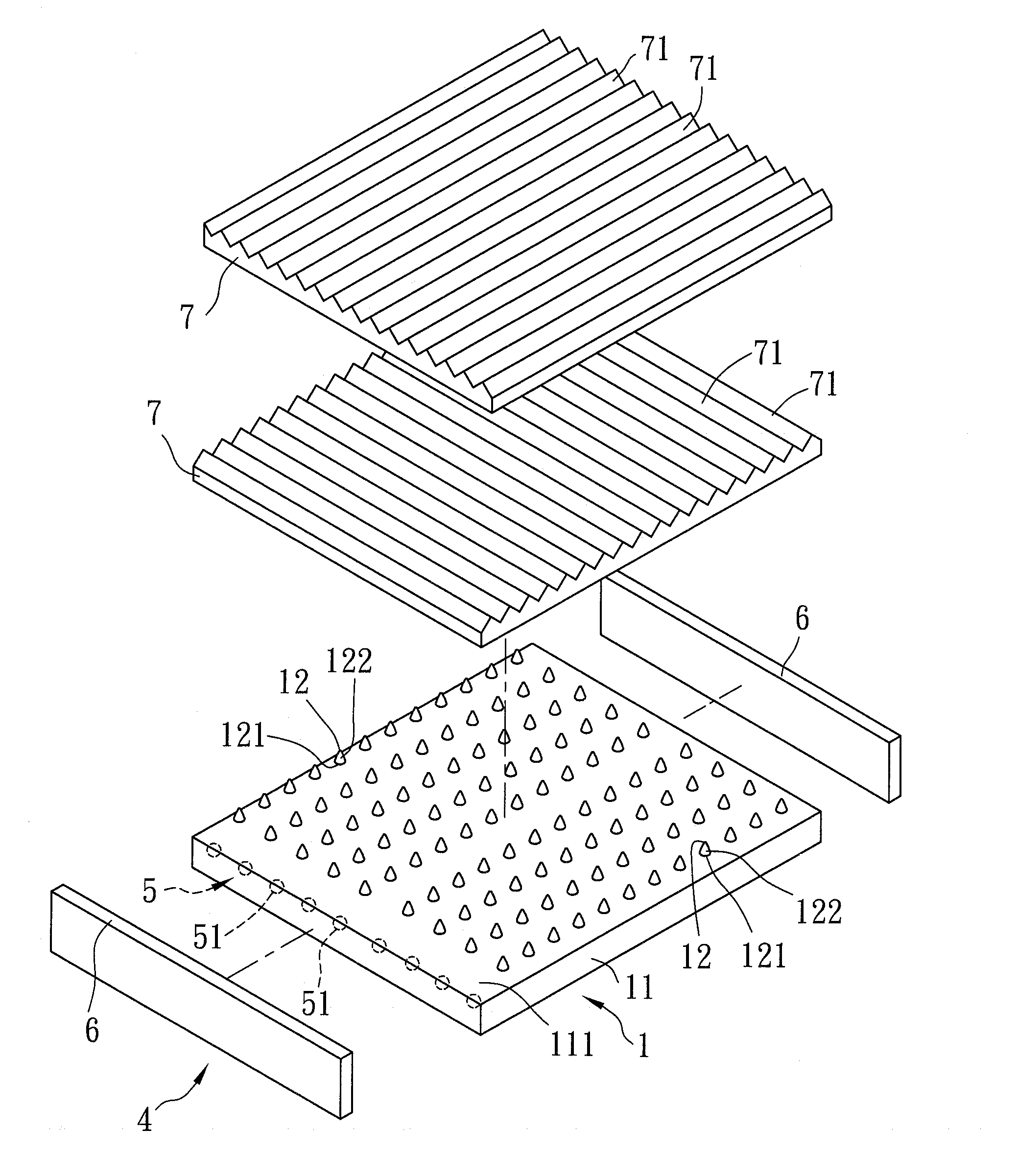
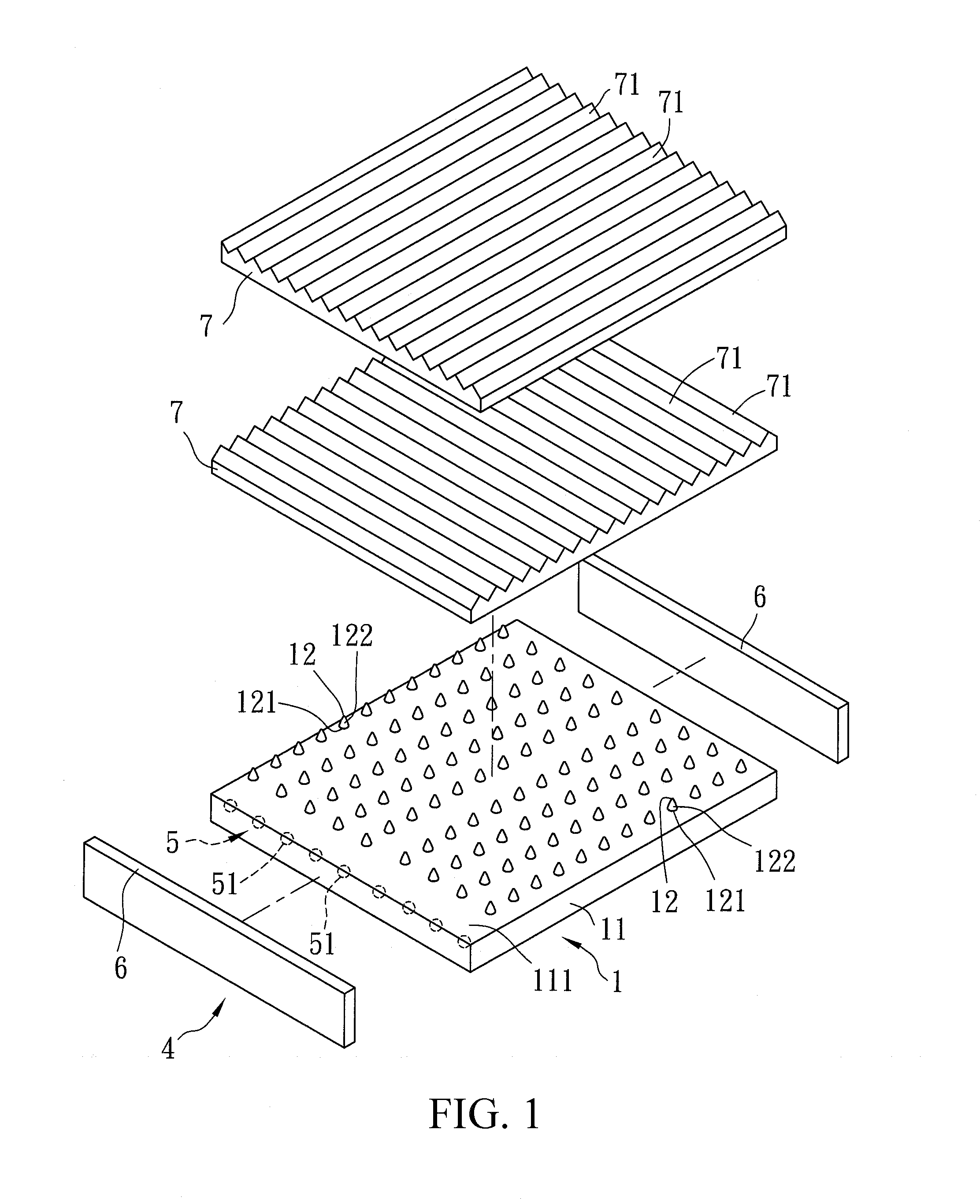
[0027]As shown in FIGS. 1 to 2, a preferred embodiment of a backlight module (4) in accordance with the invention is for use to provide uniform plain-surface light with a display panel, and comprises a flexible optical plate (1), a light element (5), two reflectors (6) and two brightness enhancement films (7) each having a prism structure (71).

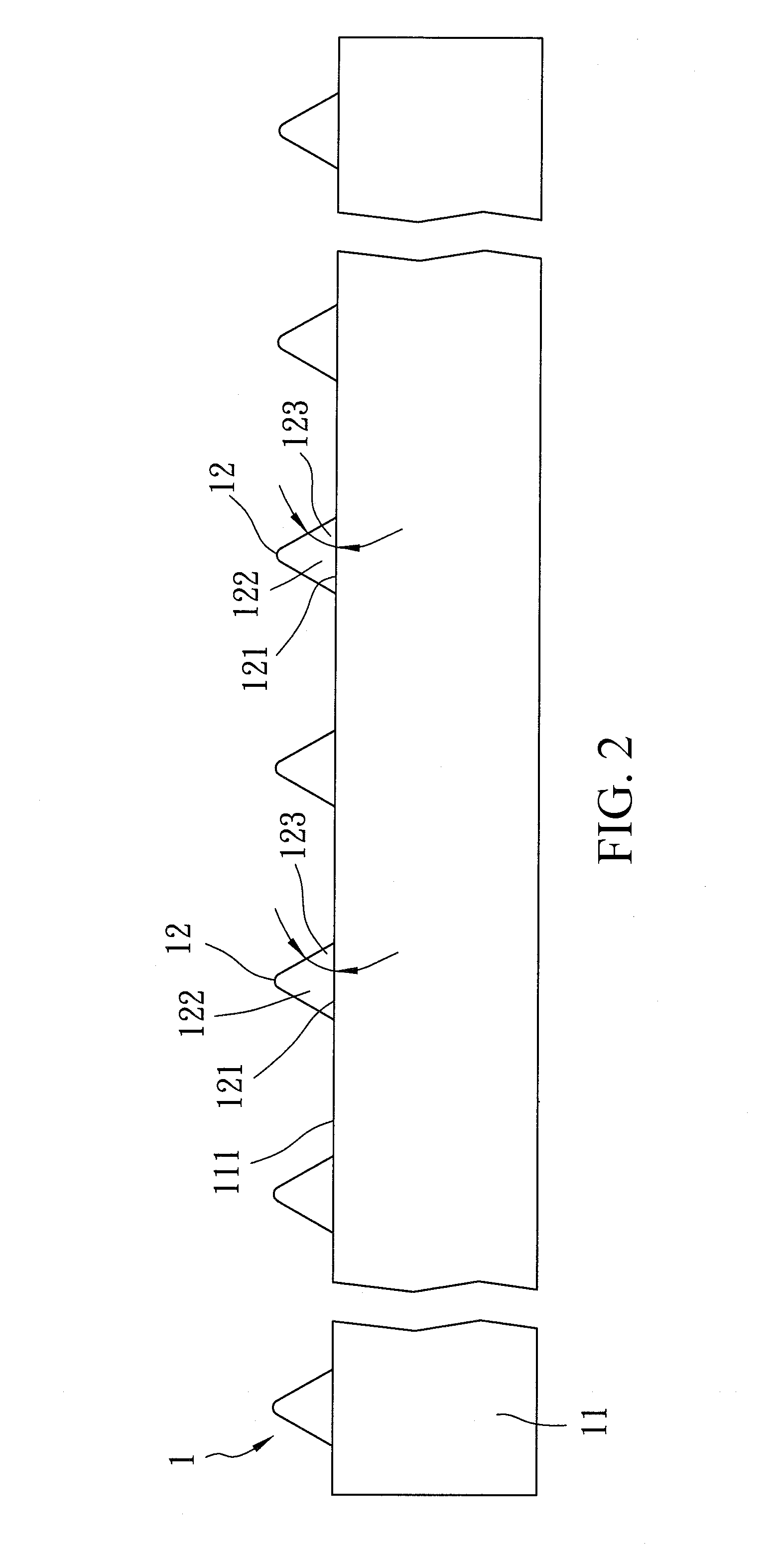
[0028]In the preferred embodiment, the flexible optical plate (1) is employed as a light guiding plate and comprises a substrate (11) and microstructures (12) formed on the substrate (11). The substrate (11) has a transparent surface (111). The microstructures (12) integrally protrude from the transparent surface (111) to form a plane outline. Each of the microstructures (12) has a hemline (121) formed approximately in a circular shape on the transparent surface (1...


PUM

PropertyMeasurementUnit
Angleaaaaaaaaaa
Sizeaaaaaaaaaa
Flexibilityaaaaaaaaaa

Abstract

A method for manufacturing a flexible optical plate includes steps of: (A) positioning a metallic mask on a surface of a mother substrate; (B) irradiating a carbon dioxide laser beam through the metallic mask to form cavities on the surface of the mother substrate; (C) coating a polymer material on the surface of the mother substrate to fill the cavities; and (D) drying the coated polymer material to form the flexible optical plate, the flexible optical plate having a substrate on the surface of the mother substrate and microstructures protruding from the substrate and each corresponding to one of the cavities.

Description

FIELD OF THE INVENTION[0001]The invention relates to a method for manufacturing a flexible optical plate, a product made and a backlight module made with the method.BACKGROUND OF THE INVENTION[0002]Current electronic devices are designed to become more and more user-friendly. Furthermore, in order to cope with different circumstances, transportability and flexibility are elements inevitable for the design of such electronic devices.[0003]Usually, a display contains numerous functions, such as a light guiding plate and a diffusion plate. For instance, a light guiding plate has a microstructure protruding from its surface for uniform light guide. Commonly, the microstructure in the optical plate is manufactured by lithography. Taiwan Patent No. I294430 discloses a method for manufacturing such an optical plate, and the method is described below. Firstly, a resist layer is coated on a surface of a substrate. Light is irradiated through a mask to expose the resist layer, and the exposed...

Claims


Application Information

Patent Timeline
IPC IPC(8): F21V7/22B32B3/00B29C35/08
CPCG02B6/0065Y10T428/24355G02B6/0053G02B6/0036B29C2059/023B29D11/00326B29D11/00663B29D11/00798
Inventor CHUNG, CHEN-KUEICHENG, CHIH-CHINGLIN, SHIH-LUNGSYU, YUAN-JIESHER, KUN-LIN
Owner NAT CHENG KUNG UNIV
Learn More