Power apparatus and method of supplying power

a power supply device and power supply technology, applied in emergency power supply arrangements, process and machine control, instruments, etc., can solve the problems of inability to meet the power consumption of the conventional power supply device b>1/b> at standby operation mode, and the power apparatus is easily damaged, so as to reduce power consumption, effectively arrest the surge current, and save energy

Inactive Publication Date: 2012-01-26
LIEN CHANG ELECTRONICS ENTERPRISE
View PDF5 Cites 20 Cited by
  • Summary
  • Abstract
  • Description
  • Claims
  • Application Information

AI Technical Summary

Benefits of technology

[0008]The object of the present invention provides a power apparatus, which can effectively arrest a surge current and decrease power consumption at the standby operating mode, thereby achieves the goal of energy saving.
[0012]Therefore, through the aforementioned technical proposal of the present invention, the following efficacy would be easily achieved: a. Due to modifying the circuit schematic design, the power consumption would be reduced and the objective of energy saving would be attained during the standby operating mode. b. The goal of “fast boot” would be achieved with the advantages of low input current and fast accumulating of appropriate switching voltage, while the machine is booting.

Problems solved by technology

However, the power apparatus is easily damaged while the end load is destroyed by excessive current generated by surge voltage.
Therefore, the power consumption of the conventional power apparatus 1 at the standby operating mode is not able to meet IEA (International Energy Association) requirement for keep power consumption below 0.1 W for each electrical appliance.

Method used


Image

  • Power apparatus and method of supplying power
  • Power apparatus and method of supplying power
  • Power apparatus and method of supplying power

Examples


Embodiment Construction

[0019]The aforementioned illustrations and the following detailed descriptions are examples for the purpose of further explaining the scope of the present invention. Other objectives and advantages related to the present invention will be illustrated in the subsequent descriptions and appended drawings.

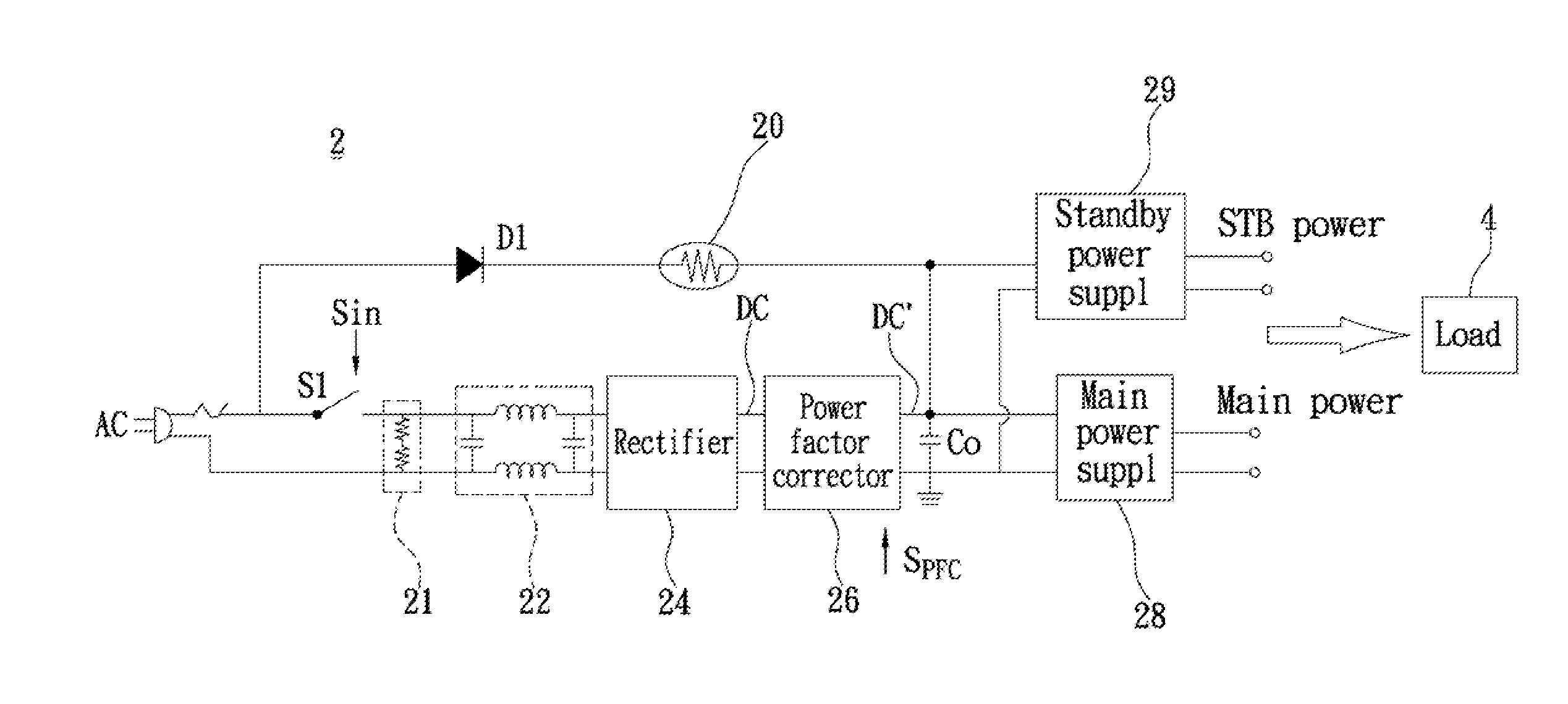
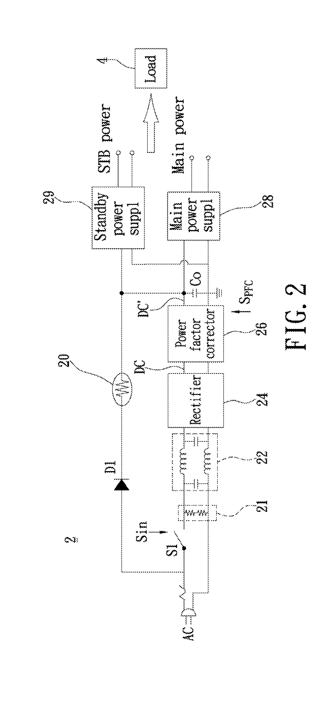
[0020]Please refer to FIG. 2, in which a power apparatus circuit block diagram of a present invention embodiment. The power apparatus 2 can be installed inside an electronic device (not shown) to provide electrical power to a load 4 of the electronic device. The electronic device may be a thin TV screen monitor or other screen type monitors. The load 4 may be a LED drive circuit.

[0021]Again, refer to FIG. 2, while the plug of the electrical equipment plugs into the power socket, the AC with surge currents would be transmitted into the power apparatus 2 of the present invention embodiment. Therefore, the power apparatus 2 may effectively arrest the surge current to protect the end load...


PUM


Abstract

The present invention provides a power apparatus, which includes a switch unit, a bleeder resistor, a filter, a rectifier, a power factor corrector, an output capacitor, a rectifying diode, a surge absorber, a main power supply, and a standby power supply. Moreover, the AC power charges to the output capacitor by means of the rectifying diode and the surge arrester, such that the standby power supply generates a standby power while the switch unit is off. Furthermore, the AC power charges to the output capacitor through the switch unit, the bleeder resistor, the filter, the rectifier and the power factor corrector, such that the main power supply generates a main power while the switch unit is on. The present invention further provides a method of supplying power.

Description

BACKGROUND OF THE INVENTION[0001]1. Field of the Invention[0002]The present invention relates to a particular power apparatus and a particular method for supplying power in order to save energy while the electrical equipment works at standby operating mode.[0003]2. Description of Related Art[0004]In general, electrical equipment is usually configured with a power apparatus and a load, wherein the power apparatus converts the Alternative Current (AC) power to a required power for the load. However, the power apparatus is easily damaged while the end load is destroyed by excessive current generated by surge voltage. For solving this problem, a surge arrester and a fuse are applied in the conventional power apparatus for arresting the surge voltage. Please refer to FIG. 1, in which a block diagram of a conventional power apparatus according to the prior art is demonstrated.[0005]A conventional power apparatus 1 can work for supplying power either at standby operating mode or normal ope...

Claims


Application Information

Patent Timeline
Patent Type & Authority Applications(United States)
IPC IPC(8): H05B41/36H02M7/06
CPCH02J9/005H05B41/28H02M2001/009H02M1/009Y02B70/30Y04S20/20
Inventor CHAN, CHUN-KONGYU, CHIH-PING
Owner LIEN CHANG ELECTRONICS ENTERPRISE
Why Eureka
Try Eureka