Network system and congestion control method

a network system and congestion control technology, applied in data switching networks, frequency-division multiplexes, instruments, etc., can solve the problems of congestion control in one route having a negative effect on data rate in the other route, and the congestion control in one route is not efficient, so as to achieve efficient congestion control in the network system

Inactive Publication Date: 2012-01-26
NEC CORP
View PDF4 Cites 36 Cited by
  • Summary
  • Abstract
  • Description
  • Claims
  • Application Information

AI Technical Summary

Benefits of technology

[0020]According to the present invention, it is possible to

Problems solved by technology

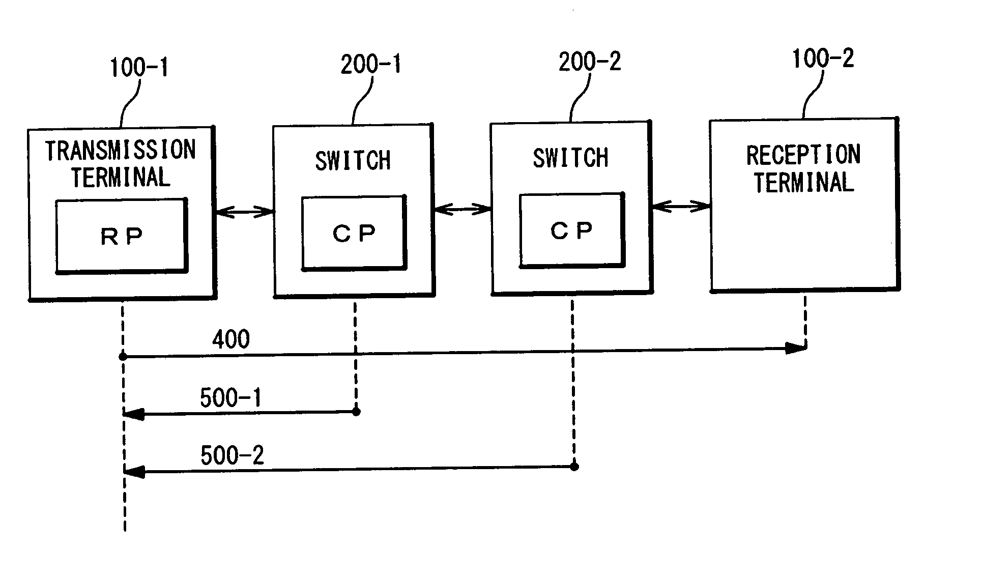
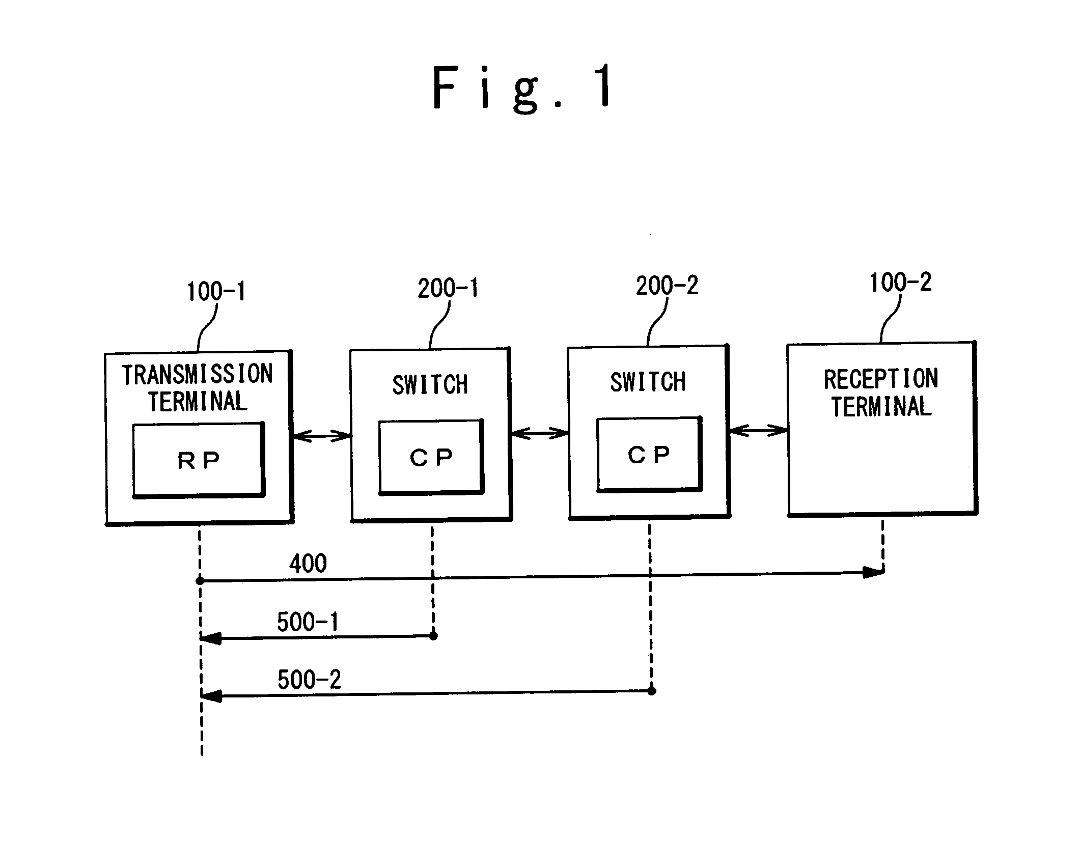
However, in the case where the plurality of routes exist in the network, there is a possibility that congestion control as shown in FIG. 1 does not efficiently work.
In other w

Method used


Image

  • Network system and congestion control method
  • Network system and congestion control method
  • Network system and congestion control method

Examples


modification example

[0094]3-3. Modification Example

[0095]FIG. 10 is a block diagram showing a modification example of the terminal 1 according to the present exemplary embodiment. FIG. 10 is different from FIG. 9 in a configuration of the flow control unit 20. Specifically, in the present modification example, the flow control unit 20 has the plurality of RP flow queues 21-1 to 21-n, a plurality of state management units 23-1 to 23-n, one rate control unit 24 and one flow selection unit 30. The state management units 23-1 to 23-n are equivalent to the respective state management units 23 of the congestion control units 22-1 to 22-n in FIG. 9.

[0096]The flow selection unit 30 obtains the data frame 400 from the RP flow queues 21-1 to 21-n. Moreover, the flow selection unit 30 selects one associated with the data frame 400 from the plurality of state management units 23-1 to 23-n. Then, the flow selection unit 30 forwards the data frame 400 to the rate control unit 24 and also passes control information f...


PUM


Abstract

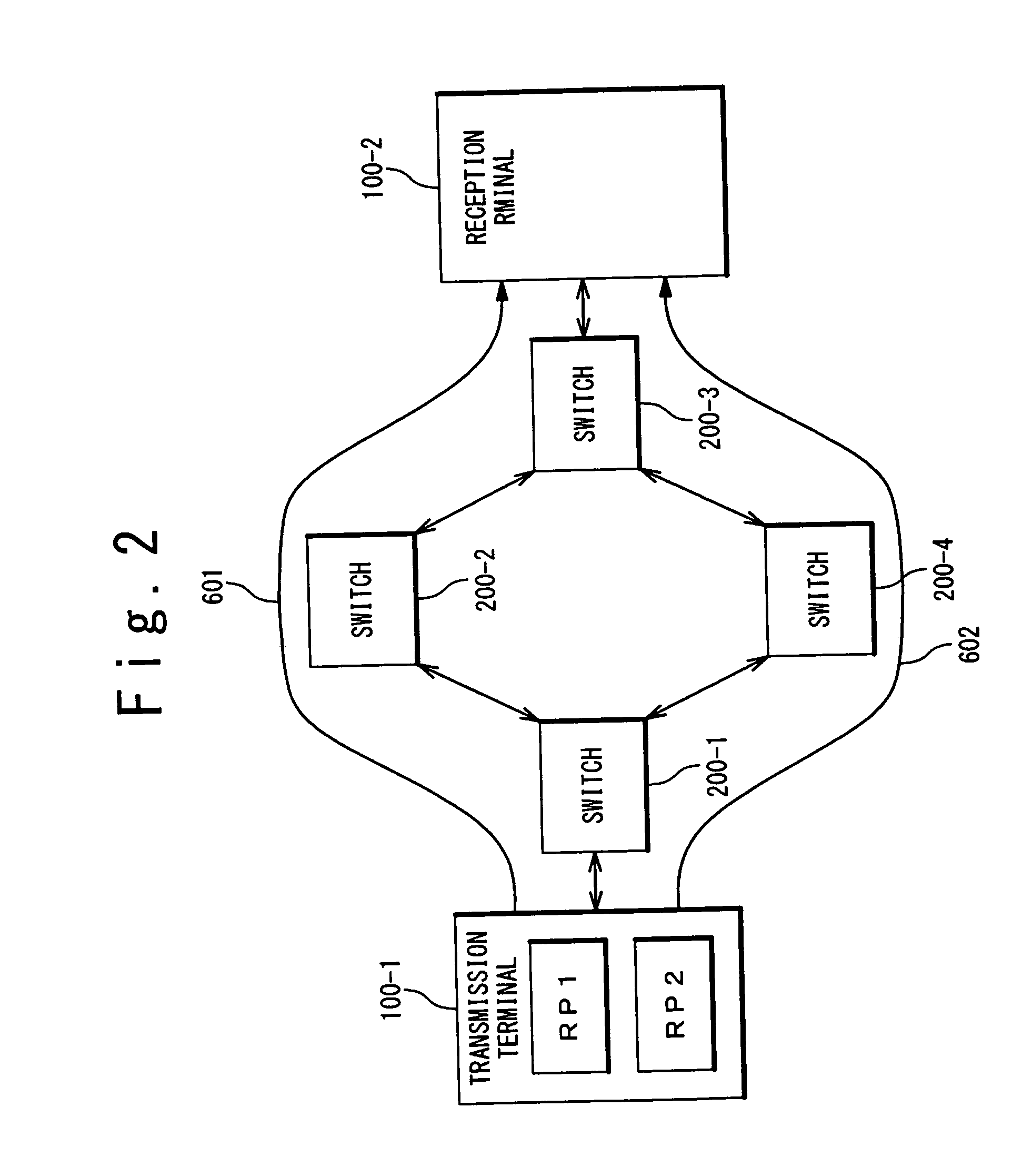
A transmission terminal has a plurality of congestion control units (RPs) each controlling a frame transmission rate. A switch arranged between the transmission terminal and a reception terminal has a plurality of congestion detection units (CPs) each generating a congestion information notification frame addressed to the transmission terminal. A plurality of routes exist between the transmission terminal and the reception terminal. The management computer manages a correspondence relationship between the routes and the RPs, assigns any of the routes to a flow, selects a RP associated with a route assigned to the flow, and notifies the transmission terminal and the switch of the flow and the selected RP. When the switch receives a frame belonging to the flow, a CP associated with the selected RP generates the congestion information notification frame addressed to the selected RP. The transmission terminal transmits a frame belonging to the flow through the selected RP.

Description

CROSS-REFERENCE TO RELATED APPLICATION[0001]This is a continuation of International Application No. PCT / JP2011 / 051454, filed on Jan. 26, 2011.TECHNICAL FIELD[0002]The present invention relates to a congestion control technique in a network system.BACKGROUND ART[0003]In recent years, a data center that integrates servers at one site and provides computer resources to individuals and companies has been increasingly used. The data center demands a network that connects a large number of servers while ensuring high-speed processing, low delay and low loss rate and has flexibility and extensibility in terms of connection.[0004]In order to meet the above-mentioned demand, the IEEE802.1 settles on a plan on the “Data Center Bridging (DCB)” technique extending a conventional MAC bridge function. The IEEE802.1Qau is standardizing the “Congestion Notification (CN)” as one technical element of the DCB. Refer to Non-Patent Literature 1 for details of the IEEE802.1Qau. A congestion control metho...

Claims


Application Information

Patent Timeline
IPC IPC(8): H04L12/26H04L45/125
CPCH04L43/0882H04L49/50H04L45/38H04L45/125
Inventor KAMIYA, SATOSHIICHINO, KIYOHISA
Owner NEC CORP
Why Eureka
Try Eureka