Radiation imaging system and collimator unit

a radiation imaging and collimator technology, applied in imaging devices, instruments, and handling using diaphragms/collimeters, etc., can solve the problems of reducing the sharpness of an x-ray image, increasing the size of the x-ray focus, and poor image quality, so as to prevent further reduction of the intensity of radiation, improve image sharpness, and reduce radiation intensity

Inactive Publication Date: 2012-01-26
FUJIFILM CORP
View PDF7 Cites 14 Cited by
  • Summary
  • Abstract
  • Description
  • Claims
  • Application Information

AI Technical Summary

Benefits of technology

[0010]An object of the present invention is to provide a radiation imaging system that can produce an image with high quality, by preventing attenuation of X-rays due to vignetting of a source grating and a heel effect of an X-ray tube, and preventing blurriness of a focus size and degradation of the coherence of the X-rays in each distributed light source due to adoption of a filter.
[0020]According to the radiation imaging system and collimator unit of the present invention, since the radiation shielding portions of the source grating extend in parallel with the rotational axis of the rotating anode, the heel effect occurs in parallel with the extending direction of the X-ray shielding portions. Thus, although the intensity of the radiation is reduced by the heel effect in a certain direction, it is possible to prevent further reduction of the intensity of the radiation in the same direction by vignetting. Furthermore, since the filter is disposed upstream from the source grating in the application direction of the radiation, the source grating can form arrayed narrow radiation beams from the radiation disturbed by the filter. This achieves improvement in sharpness of an image, as compared with a conventional case in which the filter is disposed downstream from the source grating. Furthermore, the source grating, the filter, the beam limiting unit, the lighting unit, and the like are integrated into the collimator unit. This improves ease of handling of equipment during radiography.
[0021]Disposition of the first grating, the intensity modulator, and the like between the source grating and the radiation image detector allows production of a phase contrast image. Furthermore, the phase contrast image can be produced in various structures of the system, for example, using the second grating and the scan mechanism as the intensity modulator, using the absorption gratings as the first and second gratings, using the phase diffraction grating as the first grating and the Talbot effect, using the radiation image detector having the charge collection electrodes with the periodic pattern, or the like.

Problems solved by technology

Increase in the size of the X-ray focus degrades sharpness of an X-ray image.
This leads to poorer image quality, and adversely affects medical diagnosis.
This makes the focus size blurry, and causes degradation of the coherence of the X-rays in each distributed light source, resulting in deterioration in sharpness of an image.

Method used


Image

  • Radiation imaging system and collimator unit
  • Radiation imaging system and collimator unit
  • Radiation imaging system and collimator unit

Examples


first embodiment

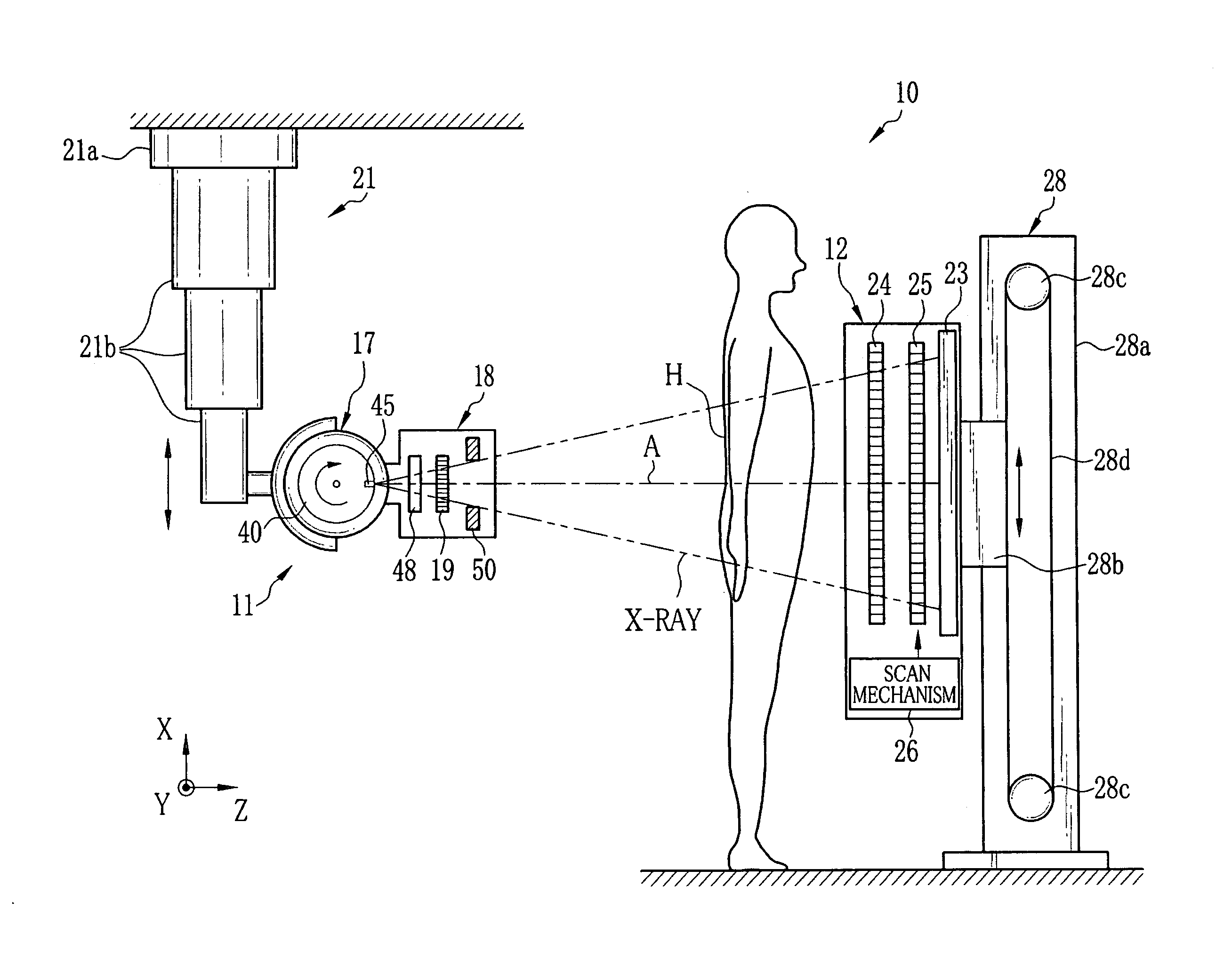
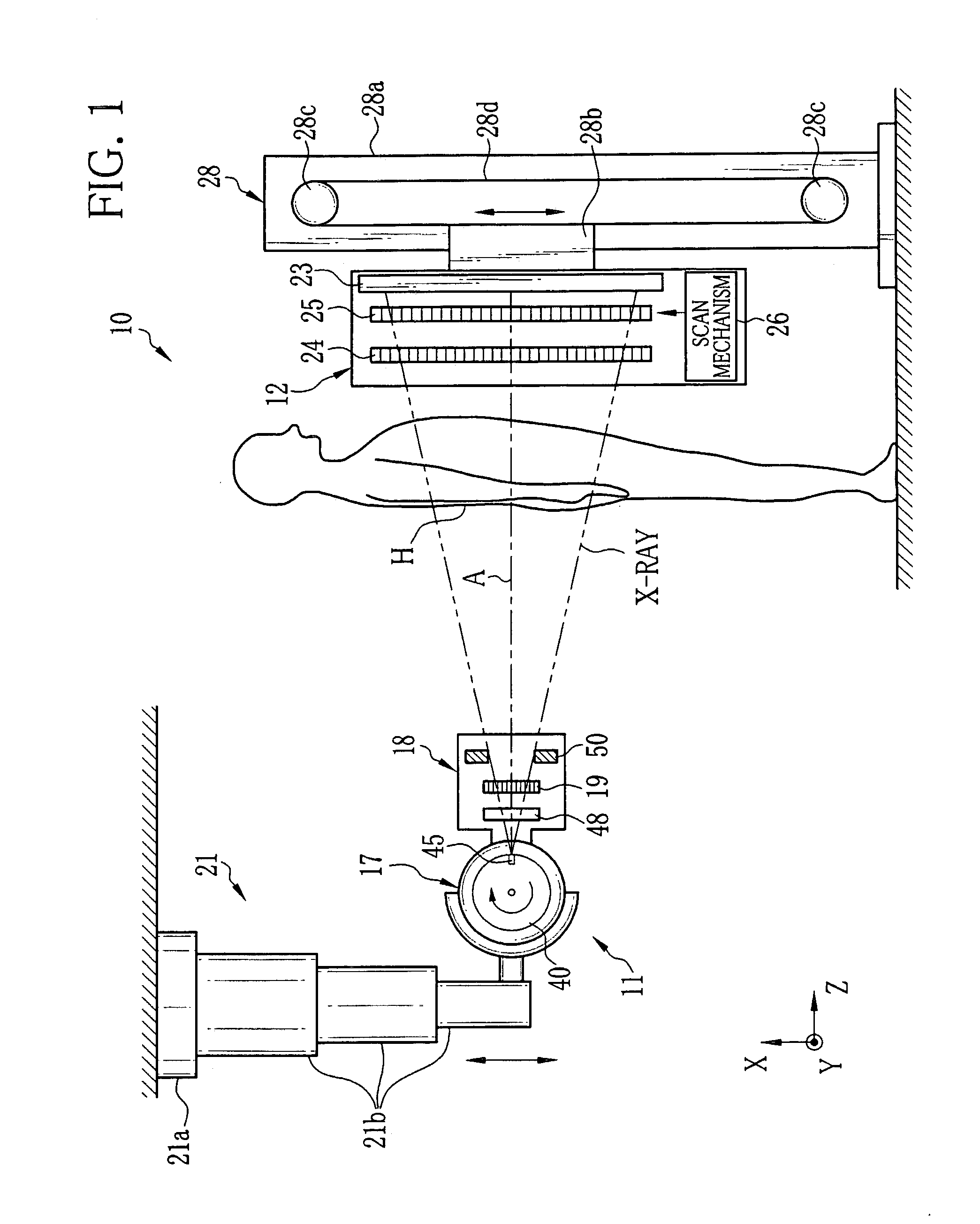
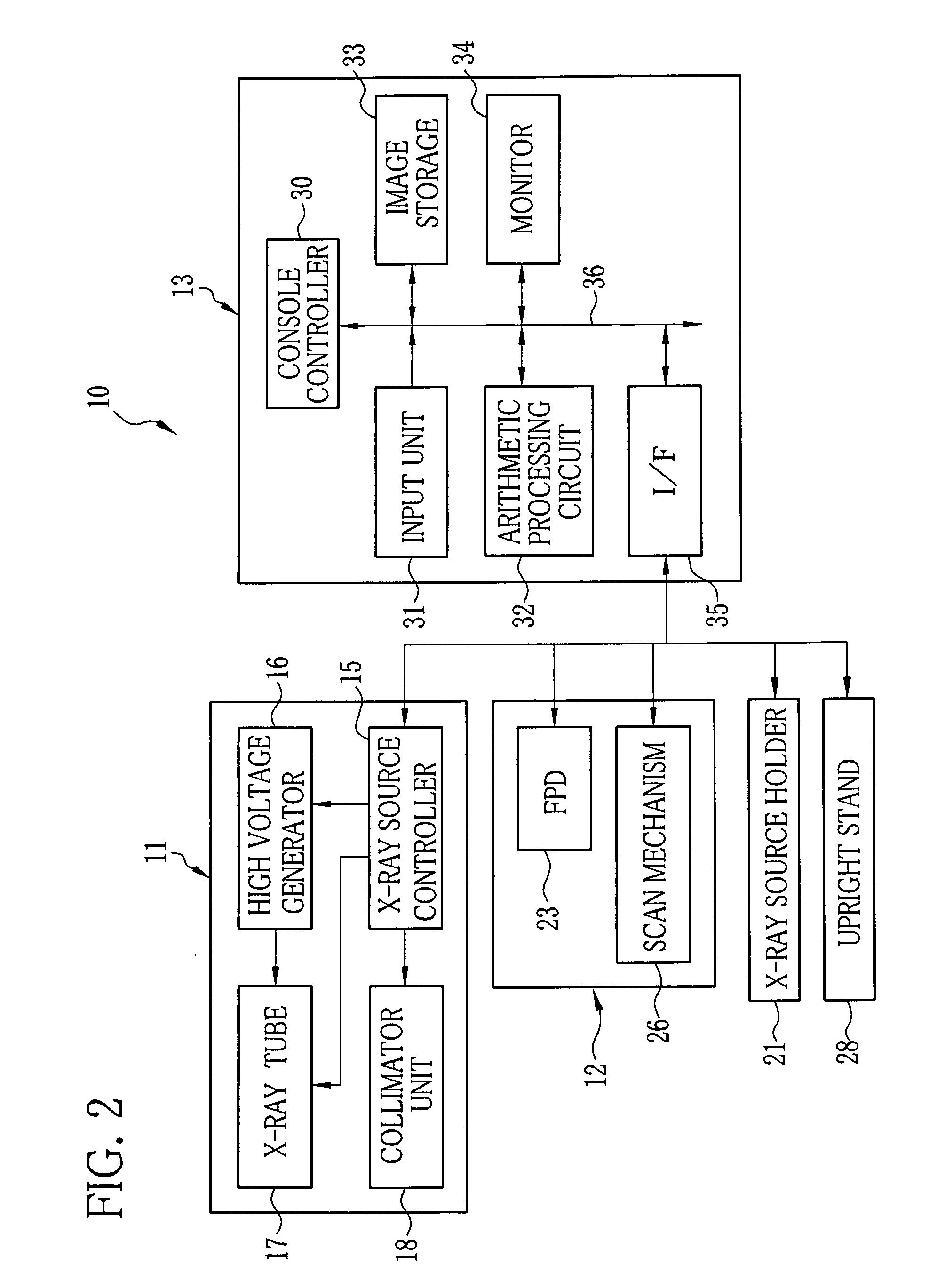
[0041]As shown in FIGS. 1 and 2, an X-ray imaging system 10 performs imaging of a standing patient. The X-ray imaging system 10 includes an X-ray source 11, an imaging unit 12, and a console 13. The X-ray source 11 applies X-rays to a body part to be imaged (object) H of the patient. The imaging unit 12 is disposed oppositely to the X-ray source 11, and detects the X-rays that have emitted from the X-ray source 11 and passed through the object H to produce image data. The console 13 controls X-ray application from the X-ray source 11 and imaging operation of the imaging unit 12 in response to operation by an operator. Also, the console 13 applies arithmetic processing to the image data produced by the imaging unit 12, and produces a phase contrast image.

[0042]The X-ray source 11 is constituted of an X-ray source controller 15, a high voltage generator 16, an X-ray tube 17, and a collimator unit 18. The X-ray tube 17 emits the X-rays in accordance with a high voltage applied from the...

second embodiment

[0093]FIG. 10 shows an X-ray imaging system 75 according to a second embodiment of the present invention. The X-ray imaging system 75 has a bed 76 for laying the patient, and takes an X-ray image of the lying patient. Since the X-ray source 11 and the imaging unit 12 have the same structure as those of the first embodiment, each component thereof is designated by the same reference numeral as that of the first embodiment. Only difference from the first embodiment will be described. The other structure and operation are the same as those of the first embodiment, and detailed description thereof will be omitted.

[0094]In this embodiment, the imaging unit 12 is attached to a bottom surface of a top table 77 so as to face the X-ray source 11 across a body part to be imaged (object) H of the patient. The X-ray source 11 is held by the X-ray source holder 21, and an angle changing mechanism (not shown) of the X-ray source 11 aims the X-ray application direction downward. In this state, the...

third embodiment

[0097]FIGS. 11 and 12 show an X-ray imaging system 80 according to a third embodiment of the present invention. The X-ray imaging system 80 takes an X-ray image of the standing or lying patient. In the X-ray imaging system 80, the X-ray source 11 and the imaging unit 12 are held by a swing arm 81. The swing arm 81 is coupled to a base 82 in a swingable manner. Since the X-ray source 11 and the imaging unit 12 have the same structure as those of the first embodiment, each component thereof is designated by the same reference numeral as that of the first embodiment. Only difference from the first embodiment will be described. The other structure and operation are the same as those of the first embodiment, and detailed description thereof will be omitted.

[0098]The swing arm 81 is constituted of a′ U-shaped member 81a and a linear member 81b connected to one end of the U-shaped member 81a. The imaging unit 12 is attached to the other end of the U-shaped member 81a. In the linear member ...


PUM

PropertyMeasurementUnit
thicknessaaaaaaaaaa
spacing distances d1aaaaaaaaaa
voltageaaaaaaaaaa

Abstract

A collimator unit includes a filter set for regulating a spectrum of X-rays emitted from an X-ray source, and a source grating having plural X-ray shielding portions and X-ray transmitting portions. The X-ray shielding portions and X-ray transmitting portions extend in a y direction parallel to a rotational axis of a rotating anode of the X-ray source, and are alternately arranged in an x direction orthogonal to an optical axis direction (z direction) of the X-rays. The intensity of the X-rays is reduced in the y direction by a heel effect. However, further reduction in the intensity of the X-rays by vignetting does not occur in the y direction. Since the filter set is disposed upstream from the source grating in an application direction of the X-rays, the source grating forms arrayed narrow focuses of X-ray beams from the X-rays disturbed by a filter element.

Description

BACKGROUND OF THE INVENTION[0001]1. Field of the Invention[0002]The present invention relates to a collimator unit used in a radiation tube of a rotating anode type, and a radiation imaging system having the collimator unit.[0003]2. Description Related to the Prior Art[0004]An X-ray tube used in an X-ray imaging system, which images an object with X-rays, is constituted of an anode and a cathode disposed oppositely to each other in a vacuum vessel. To produce the X-rays, thermoelectrons as an electron beam emitted from a filament of the cathode are made collide against the anode (target). A collision point of the electron beam on the anode is defined as an X-ray focus, from which the X-rays radiate.[0005]The X-ray tube has a stationary anode type and a rotating anode type. The X-ray imaging system generally uses a rotating anode type X-ray tube that can emit higher power X-rays than those from a stationary anode type X-ray tube. As shown in FIGS. 16 and 17, in a rotating anode type ...

Claims


Application Information

Patent Timeline
Patent Type & Authority Applications(United States)
IPC IPC(8): G01N23/04G21K1/02
CPCG21K1/025A61B6/484G21K2207/00
Inventor MURAKOSHI, DAI
Owner FUJIFILM CORP
Why Eureka
Try Eureka