Networked Motorized Drive Roller Conveyor

a motorized drive and conveyor technology, applied in the direction of conveyor control devices, conveyor parts, roller-ways, etc., can solve the problems of mdr systems lacked the ability to control the size of gaps between items on the conveyor system, requiring significant time, labor and money to route and terminate wiring, etc., to reduce the complexity of installation, reduce the wiring needed for the system, and reduce the implementation time and cost

Inactive Publication Date: 2012-02-02
DANELSKI DARIN L +1
View PDF3 Cites 50 Cited by
  • Summary
  • Abstract
  • Description
  • Claims
  • Application Information

AI Technical Summary

Benefits of technology

[0007]The networked, distributed control system of the present invention provides localized controls for various operations, e.g., diverting, bar code scanning, RFID transactions, labeling, etc. The inventive control system can also handle the basic MDR conveyor drive and accumulation responsibilities, which greatly reduces the wiring needed for the system, implementation time, and cost while maintaining a centralized diagnostic capability. Additional capability to allow localized programming as well as status and diagnostics capability are additional benefits of the inventive control system. Eliminating the need for P

Problems solved by technology

A typical control system utilizing a PLC requires several hundred to several thousand feet of control wiring, which requires significant time, labor and money to route and terminate the wiring.
Having multiple PLCs in this environment creates other undesirable issues as single point diagnostics are difficult to implement.
However, prior to the present invention, MDR systems lacked

Method used


Image

  • Networked Motorized Drive Roller Conveyor
  • Networked Motorized Drive Roller Conveyor
  • Networked Motorized Drive Roller Conveyor

Examples


Embodiment Construction

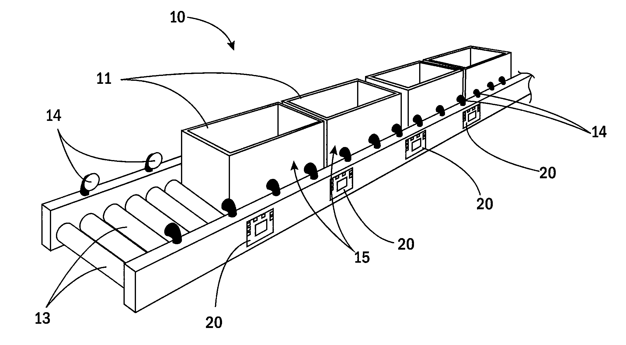
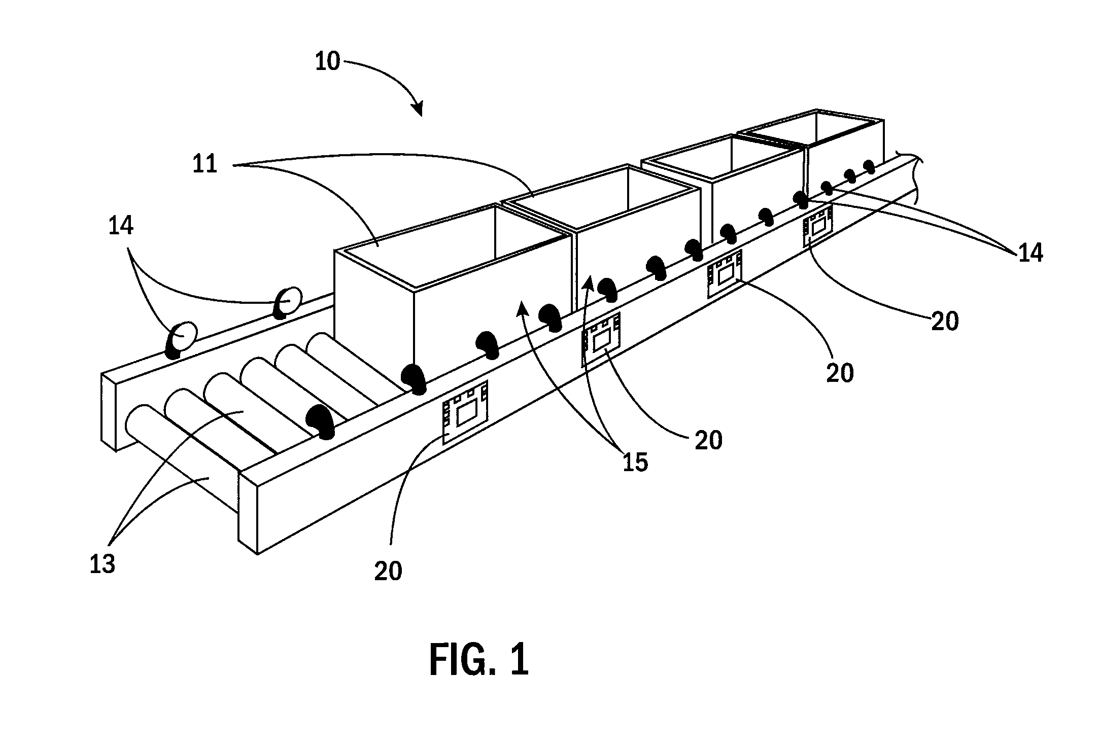
[0029]FIG. 1 shows a portion of the conveyor system 10 of the present invention that incorporates control cards 20 in accordance with the present invention. Generally speaking, a number of items 11 are supported on the conveyor 10, which includes a plurality of rollers 13, including MDRs and corresponding idler rollers. The conveyor system 10 further includes a plurality of sensors 14 that detect items 11 as the items 11 move along the conveyor system 10. The conveyor system 10 is divided into zones 15. Each zone 15 is defined between adjacent sensors 14. Additionally, each zone 15 corresponds with an MDR / idler roller assembly. In the inventive system, each zone 15 is shorter than the length of the respective items 11 being conveyed by the conveyor system 10.

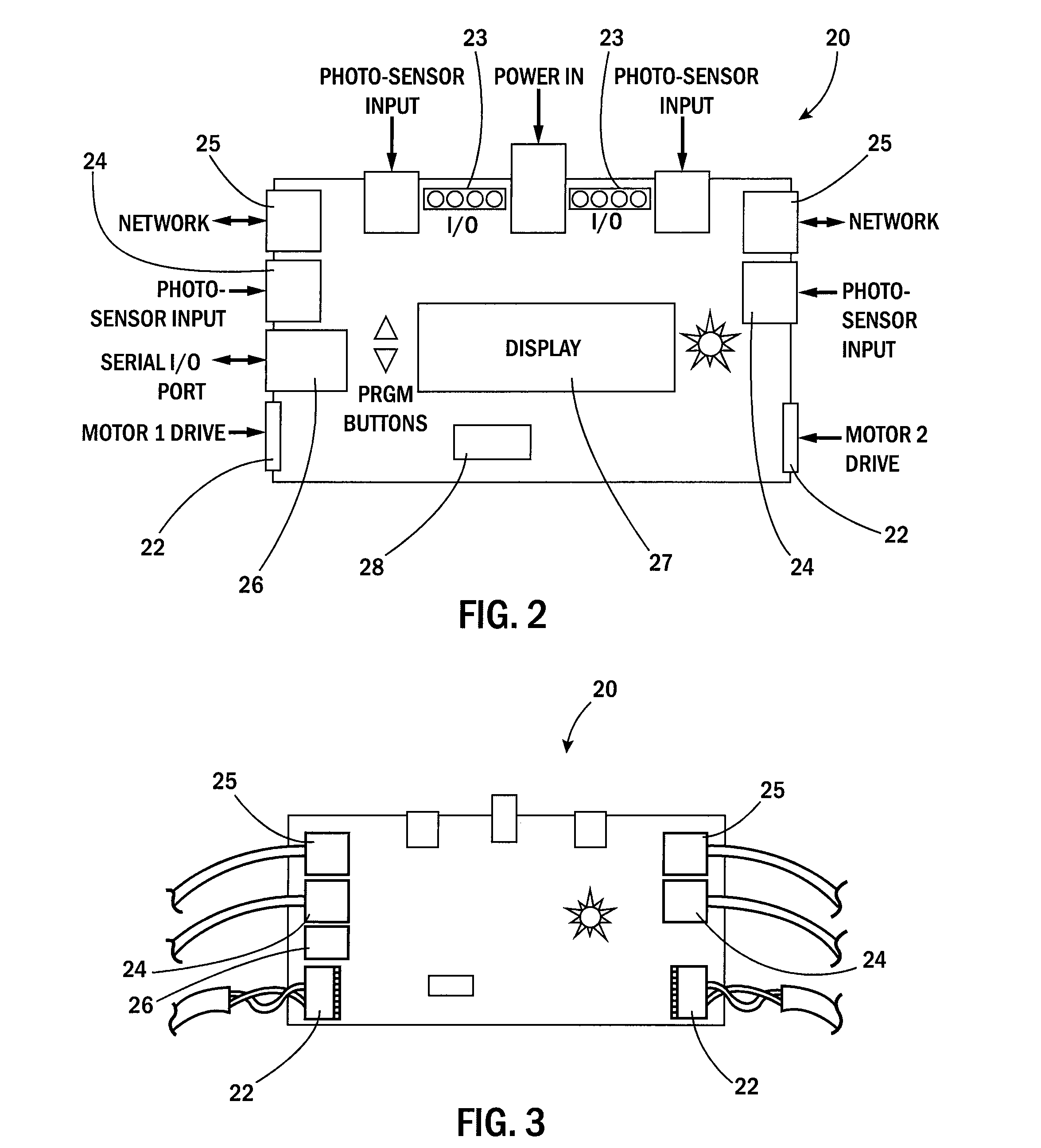
[0030]FIGS. 2 and 3 illustrate a networked, distributed MDR control card 20 with local control capabilities. Accordingly, the inventive card 20 eliminates the need for a central PLC and reduces and / or eliminates the need for wir...


PUM


Abstract

A motorized drive roller conveyor includes an upstream zone and a downstream zone, with each zone having a drive roller, an idler roller that is driven by the drive roller, and a sensor. The upstream zone and the downstream zone are controlled by a card, which measures a gap between a first item on the conveyor and a second item on the conveyor by beginning a counter when a trailing edge of the first item passes the sensor of the upstream zone and stopping the counter when a leading edge of the second item passes the sensor of the upstream zone to generate a counter value. If the first item is stopped in the downstream zone, the card of the upstream zone causes the drive roller of the upstream zone to advance the second item into the downstream zone for a distance derived from the counter value before stopping the transportation of the second item.

Description

BACKGROUND AND SUMMARY OF THE INVENTION[0001]The present invention relates generally to a networked motorized drive roller conveyor.[0002]Conventional conveyor control systems utilize a central Programmable Logic Controller (“PLC”) mounted in a central control panel. This type of system requires control devices, e.g., photo-eyes, solenoid valves, and motor starters, to be terminated at the main control panel. A typical control system utilizing a PLC requires several hundred to several thousand feet of control wiring, which requires significant time, labor and money to route and terminate the wiring. In addition, the PLC requires specialized knowledge, e.g., knowledge of ladder logic, and familiarity with the many different interface requirements unique to each manufacturer's product. Moreover, since there is a central controller, response time with respect to the control devices may be increased because the single processor must account for all operations occurring within the system...

Claims


Application Information

Patent Timeline
IPC IPC(8): B65G43/08B65G13/02
CPCB65G43/10B65G43/08B65G13/02B65G47/261B65G2811/0673
Inventor DANELSKI, DARIN L.HENRY, MELVIN W.
Owner DANELSKI DARIN L
Why Eureka
Try Eureka