Modular MRI phased array antenna

a phased array antenna and module technology, applied in the direction of using reradiation, geological measurements, magnetic measurements, etc., can solve the problems of generating artefacts in the mr image, couplings deteriorating the signal-to-noise ratio (snr), and indubitable voltage in neighboring antennas,

Active Publication Date: 2012-02-02
BRUKER SWITZERLAND AG
View PDF15 Cites 4 Cited by
  • Summary
  • Abstract
  • Description
  • Claims
  • Application Information

AI Technical Summary

Problems solved by technology

The antenna arrays have one problem due to the fact that, when several individual antennas are arranged next to one another, it may happen that a high-frequency current in one of the individual antennas induces a voltage in neighboring individual antennas.
Couplings deteriorate the signal-to-noise ratio (SNR) and generate artefacts in the MR image.
Examination of coupled individual antennas is moreover more demanding than examination of individual antennas that are not coupled.
However, the expense is great for obtaining sufficient decoupling in this fashion.
Asymmetries, however, cause couplings of the two antenna systems which are compensated for by a capacitor which connects the two antenna systems.
All of these approaches have one common problem.

Method used


Image

  • Modular MRI phased array antenna
  • Modular MRI phased array antenna
  • Modular MRI phased array antenna

Examples


Embodiment Construction

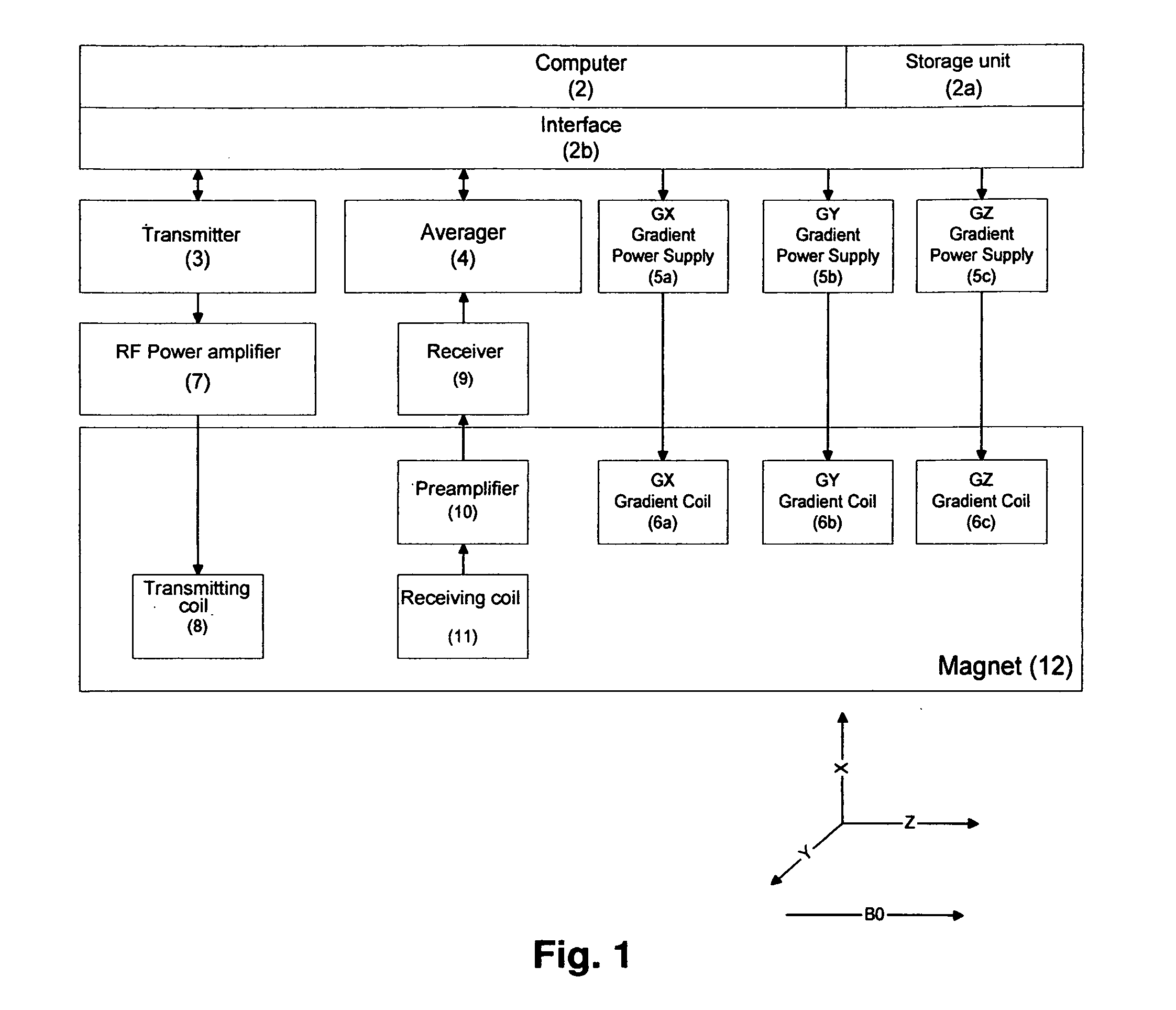
[0040]FIG. 1 is a simplified block diagram of the substantial components of a magnetic resonance imaging (MRI) system which is suitable for use with an antenna configuration described in the present invention.

[0041]The system consists of a computer which is connected to a storage unit and to an interface unit.

[0042]A radio frequency (RF) transmitter, an RF receiver and power supplies for the gradients are connected to the computer via the interface unit.

[0043]The power supply of the gradients supplies the gradient coils which generate the magnetic fields Gx, Gy and Gz with a gradient in the X, Y, and Z directions over the object to be imaged.

[0044]The RF transmitter is triggered via computer pulses, thereby generating the RF pulses of corresponding modulation in order to excite an MR signal in the object.

[0045]The RF pulses are amplified in an RF power amplifier to powers of between some hundred watts to several kilowatts in dependence on the imaging method, and are transmitted to t...


PUM


Abstract

An antenna configuration for use in a magnetic resonance apparatus, which is designed as phase-controlled array and comprises at least two individual antennas which each comprise at least one conductor loop, one tuning network and one matching network, wherein the tuning network contains at least one tuning capacitance and the matching network contains at least one matching capacitance, and the individual antennas are each combined into separate modules which are positioned on and mounted to a support body and can be removed therefrom in a non-destructive fashion, is characterized in that the individual antennas are connected to each other through decoupling elements, wherein the decoupling elements are mounted to the support body in an undetachable fashion. It is thereby possible to define individual antenna modules which can be arranged in a simple fashion around the measuring volume, are also electromagnetically decoupled from each other, and can be positioned close to the measuring volume in order to ensure that the received MRI image has a maximum, high signal-to-noise ratio.

Description

[0001]This application claims Paris convention priority of DE 10 2010 038 722.3 filed Jul. 30, 2010 the entire disclosure of which is hereby incorporated by reference.BACKGROUND OF THE INVENTION[0002]The invention concerns an antenna configuration for use in a magnetic resonance apparatus, which is designed as a phase-controlled array and comprises at least two individual antennas each of which comprises at least one conductor loop, one tuning network and one matching network, wherein the tuning network contains at least one tuning capacitance and the matching network contains at least one matching capacitance, and the individual antennas are each combined into separate modules which are positioned on and mounted to a support body and can be removed therefrom in a non-destructive fashion.[0003]An antenna configuration of this type is disclosed in U.S. Pat. No. 6,084,411.[0004]The invention concerns an imaging device which utilizes nuclear magnetic resonance (NMR or MR) by using ante...

Claims


Application Information

Patent Timeline
Patent Type & Authority Applications(United States)
IPC IPC(8): G01R33/44
CPCG01R33/34007G01R33/365G01R33/3415
Inventor SCHMIDIG, DANIEL
Owner BRUKER SWITZERLAND AG
Why Eureka
Try Eureka